Table of Contents
Advertisement
Quick Links
Advertisement
Table of Contents

Subscribe to Our Youtube Channel
Related Manuals for Supermicro SUPERSERVER 5018D-MHR7N4P


Summary of Contents for Supermicro SUPERSERVER 5018D-MHR7N4P
- Page 1 UPER ERVER ® 5018D-MHR7N4P USER’S MANUAL...
- Page 2 This product, including software and docu- mentation, is the property of Supermicro and/or its licensors, and is supplied only under a license. Any use or reproduction of this product is not allowed, except as expressly permitted by the terms of said license.
- Page 3 About This Manual This manual is written for professional system integrators and PC technicians. It pro- vides information for the installation and use of the SuperServer 5018D-MHR7N4P. Installation and maintenance should be performed by experienced technicians only. The SuperServer 5018D-MHR7N4P is a high-end server based on the SC- 813MFTQC-R407CB rackmountable chassis and the X10SDV-7TP4F SoC moth- erboard.
- Page 4 UPER ERVER 5018D-MHR7N4P User's Manual Chapter 5: Advanced Motherboard Setup Chapter 5 provides detailed information on the X10SDV-7TP4F motherboard, including the locations and functions of connections, headers and jumpers. Refer to this chapter when adding or removing processors or main memory and when reconfiguring the motherboard.
- Page 5 Preface Notes...
-
Page 6: Table Of Contents
Server Chassis Features ................1-3 System Power ....................1-3 Hard Drive Subsystem ..................1-3 Front Control Panel ..................1-3 Contacting Supermicro ..................1-5 Chapter 2 Server Installation Overview ......................2-1 Unpacking the System ..................2-1 Preparing for Setup ..................2-1 Choosing a Setup Location ................ - Page 7 Table of Contents Drive Carrier LEDs ..................3-4 Chapter 4 Standardized Warning Statements for AC Systems About Standardized Warning Statements ............4-1 Warning Definition ................... 4-1 Installation Instructions ..................4-4 Circuit Breaker ....................4-5 Power Disconnection Warning ................ 4-6 Equipment Installation ..................4-8 Restricted Area ....................
- Page 8 UPER ERVER 5018D-MHR7N4P User's Manual Unpacking ....................... 6-1 Control Panel ....................6-2 System Fans ....................6-3 Drive Bay Installation/Removal ............... 6-3 SATA Drive Installation ..................6-4 SATA Backplane ....................6-5 Power Supply ....................6-7 Power Supply Failure ..................6-7 Chapter 7 BIOS Introduction ......................
-
Page 9: Chapter 1 Introduction
Chapter 1 Introduction Overview The SuperServer 5018D-MHR7N4P is an embedded system comprised of two main subsystems: the SC813MFTQC-R407CB 1U chassis and the X10SDV-7TP4F single processor motherboard. Please refer to our website for information on operating systems that have been certified for use with the system (www.supermicro.com). -
Page 10: Motherboard Features
UPER ERVER 5018D-MHR7N4P User's Manual Motherboard Features The SuperServer 5018D-MHR7N4P is built around the X10SDV-7TP4F, a single processor motherboard designed to provide maximum performance. Below are the main features of the X10SDV-7TP4F. (See Figure 1-1 for a block diagram). Processor The X10SDV-7TP4F supports a single Intel®... -
Page 11: Server Chassis Features
Chapter 1: Introduction Server Chassis Features The SC813MFTQC-R407CB is an mini-ITX form factor chassis designed to be used in a 1U rackmount configuration. The following is a general outline of the main features of the SC813MFTQC-R407CB server chassis. System Power The SC813MFTQC-R407CB features a redundant 400W power supply. - Page 12 UPER ERVER 5018D-MHR7N4P User's Manual Figure 1-1. X10SDV-7TP4F: System Block Diagram Note: This is a general block diagram. Please see Chapter 5 for details. DDR4 1600/1866/2133 PCIE 3.0 x8 JPCIE1 PCIE 3.0 x8 PCIE 3.0 x8 JPCIE2 PCIE 3.0 x8 MINI-SAS HD PROCESSOR PCIE 3.0 x4...
-
Page 13: Contacting Supermicro
Super Micro Computer, Inc. 980 Rock Ave. San Jose, CA 95131 U.S.A. Tel: +1 (408) 503-8000 Fax: +1 (408) 503-8008 Email: marketing@supermicro.com (General Information) support@supermicro.com (Technical Support) Web Site: www.supermicro.com Europe Address: Super Micro Computer B.V. Het Sterrenbeeld 28, 5215 ML... - Page 14 UPER ERVER 5018D-MHR7N4P User's Manual Notes...
-
Page 15: Chapter 2 Server Installation
Chapter 2: Server Installation Chapter 2 Server Installation Overview This chapter provides a quick setup checklist to get your SuperServer 5018D- MHR7N4P up and running. Following the steps in the order given should enable you to have the system operational within a minimal amount of time. This quick setup assumes that your system has come to you with the processor and memory preinstalled. -
Page 16: Warnings And Precautions
UPER ERVER 5018D-MHR7N4P User's Manual installation only in a Restricted Access Location (dedicated equipment rooms, service closets and the like). • This product is not suitable for use with visual display work place devices ac- cording to §2 of the German Ordinance for Work with Visual Display Units. Warnings and Precautions Rack Precautions •... -
Page 17: Rack Mounting Considerations
Chapter 2: Server Installation Rack Mounting Considerations Ambient Operating Temperature If installed in a closed or multi-unit rack assembly, the ambient operating tempera- ture of the rack environment may be greater than the ambient temperature of the room. Therefore, consideration should be given to installing the equipment in an environment compatible with the manufacturer’s maximum rated ambient tempera- ture (Tmra). -
Page 18: Installing The System Into A Rack
Installing the Rack Rails Determine where you want to place the SuperServer 5018D-MHR7N4P in the rack (see Rack and Server Precautions in Section 2-3). Position the chassis rail guides at the desired location in the rack, keeping the sliding rail guide facing the inside of the rack. -
Page 19: Installing The Server Into The Rack
Chapter 2: Server Installation Installing the Server into the Rack Install the server into the rack by lining up the rear of the chassis rails with the front of the rack rails. Slide the chassis rails into the rack rails, keeping the pressure even on both sides (you may have to depress the locking tabs when inserting). -
Page 20: Installing The Server Into A Telco Rack
ERVER 5018D-MHR7N4P User's Manual Installing the Server into a Telco Rack To install the SuperServer 5018D-MHR7N4P into a Telco type rack, use two L- shaped brackets on either side of the chassis (four total). First, determine how far the server will extend out the front of the rack. Larger chassis should be positioned to balance the weight between front and back. -
Page 21: Chapter 3 System Interface
Chapter 3: System Interface Chapter 3 System Interface Overview There are several LEDs on the control panel as well as others on the drive carriers to keep you constantly informed of the overall status of the system as well as the activity and health of specific components. -
Page 22: Control Panel Buttons
UPER ERVER 5018D-MHR7N4P User's Manual Control Panel Buttons There are two push-buttons located on the front of the chassis. These are (in order from left to right) a reset button and a power on/off button. Reset: The reset button is used to reboot the system. Power: The main power switch is used to apply or remove power from the power supply to the server system. - Page 23 Chapter 3: System Interface NIC2: Indicates network activity on GLAN2 when flashing. NIC1: Indicates network activity on GLAN1 when flashing. HDD: Indicates hard drive (SAS/SATA) activity when flashing. Power: Indicates power is being supplied to the system's power supply units. This LED should normally be illuminated when the system is operating.
-
Page 24: Drive Carrier Leds
UPER ERVER 5018D-MHR7N4P User's Manual Drive Carrier LEDs Your system supports SAS or SATA, but not both at the same time. SAS/SATA Drives Each SAS/SATA drive carrier has two LEDs. • Green: Each drive carrier has a green LED. When illuminated, this green LED (on the front of the drive carrier) indicates drive activity. -
Page 25: About Standardized Warning Statements
The following statements are industry standard warnings, provided to warn the user of situations which have the potential for bodily injury. Should you have questions or experience difficulty, contact Supermicro's Technical Support department for assistance. Only certified technicians should attempt to install or configure components. - Page 26 UPER ERVER 5018D-MHR7N4P User's Manual Warnung WICHTIGE SICHERHEITSHINWEISE Dieses Warnsymbol bedeutet Gefahr. Sie befinden sich in einer Situation, die zu Verletzungen führen kann. Machen Sie sich vor der Arbeit mit Geräten mit den Gefahren elektrischer Schaltungen und den üblichen Verfahren zur Vorbeugung vor Unfällen vertraut.
- Page 27 Warning Statements for AC Systems . ٌ ا ك ً ف حالة و ٌ يك أى تتسبب ف اصابة جسذ ة ٌ هذا الزهز ع ٌ خطز !تحذ ز قبل أى تعول عىل أي هعذات،يك عىل علن بالوخاطز ال ا ٌ جوة عي الذوائز ٍ...
-
Page 28: Installation Instructions
UPER ERVER 5018D-MHR7N4P User's Manual Installation Instructions Warning! Read the installation instructions before connecting the system to the power source. 設置手順書 システムを電源に接続する前に、 設置手順書をお読み下さい。 警告 将此系统连接电源前,请先阅读安装说明。 警告 將系統與電源連接前,請先閱讀安裝說明。 Warnung Vor dem Anschließen des Systems an die Stromquelle die Installationsanweisungen lesen. ¡Advertencia! Lea las instrucciones de instalación antes de conectar el sistema a la red de alimentación. -
Page 29: Circuit Breaker
Chapter 4: Warning Statements for AC Systems Circuit Breaker Warning! This product relies on the building's installation for short-circuit (overcurrent) protection. Ensure that the protective device is rated not greater than: 250 V, 20 A. サーキッ ト ・ ブレーカー この製品は、 短絡 (過電流) 保護装置がある建物での設置を前提としています。 保護装置の定格が250 V、... -
Page 30: Power Disconnection Warning
UPER ERVER 5018D-MHR7N4P User's Manual هذا املنتج يعتمد عىل معداث الحاميت مه الدوائ ر القصرية التي تم تثبيتها يف املبنى 20A, 250V : تأكد من أن تقييم الجهاز الوقايئ ليس أكرث من 경고! 이 제품은 전원의 단락(과전류)방지에 대해서 전적으로 건물의 관련 설비에 의존합니다. - Page 31 Chapter 4: Warning Statements for AC Systems ¡Advertencia! El sistema debe ser disconnected de todas las fuentes de energía y del cable eléctrico quitado de los módulos de fuente de alimentación antes de tener acceso el interior del chasis para instalar o para quitar componentes de sistema. Attention Le système doit être débranché...
-
Page 32: Equipment Installation
UPER ERVER 5018D-MHR7N4P User's Manual Equipment Installation Warning! Only trained and qualified personnel should be allowed to install, replace, or service this equipment. 機器の設置 トレーニングを受け認定された人だけがこの装置の設置、 交換、 またはサービスを許可 されています。 警告 只有经过培训且具有资格的人员才能进行此设备的安装、更换和维修。 警告 只有經過受訓且具資格人員才可安裝、更換與維修此設備。 Warnung Das Installieren, Ersetzen oder Bedienen dieser Ausrüstung sollte nur geschultem, qualifiziertem Personal gestattet werden. -
Page 33: Restricted Area
Chapter 4: Warning Statements for AC Systems Waarschuwing Deze apparatuur mag alleen worden geïnstalleerd, vervangen of hersteld door geschoold en gekwalificeerd personeel. Restricted Area Warning! This unit is intended for installation in restricted access areas. A restricted access area can be accessed only through the use of a special tool, lock and key, or other means of security. -
Page 34: Battery Handling
UPER ERVER 5018D-MHR7N4P User's Manual אזור עם גישה מוגבלת !אזהרה יש להתקין את היחידה באזורים שיש בהם הגבלת גישה. הגישה ניתנת בעזרת (.'כלי אבטחה בלבד (מפתח, מנעול וכד . تخصيص هذه انىحذة نترك ب ُها ف مناطق محظورة تم ، م َ كن انىصىل إن منطقت محظورة فقط من خالل استخذاو أداة خاصت أو... - Page 35 Chapter 4: Warning Statements for AC Systems Warnung Bei Einsetzen einer falschen Batterie besteht Explosionsgefahr. Ersetzen Sie die Batterie nur durch den gleichen oder vom Hersteller empfohlenen Batterietyp. Entsorgen Sie die benutzten Batterien nach den Anweisungen des Herstellers. Attention Danger d'explosion si la pile n'est pas remplacée correctement. Ne la remplacer que par une pile de type semblable ou équivalent, recommandée par le fabricant.
-
Page 36: Redundant Power Supplies
UPER ERVER 5018D-MHR7N4P User's Manual Redundant Power Supplies Warning! This unit might have more than one power supply connection. All connections must be removed to de-energize the unit. 冗長電源装置 このユニッ トは複数の電源装置が接続されている場合があります。 ユニッ トの電源を切るためには、 すべての接続を取り外さなければなりません。 警告 此部件连接的电源可能不止一个,必须将所有电源断开才能停止给该部件供电。 警告 此裝置連接的電源可能不只一個,必須切斷所有電源才能停止對該裝置的供電。 Warnung Dieses Gerät kann mehr als eine Stromzufuhr haben. Um sicherzustellen, dass der Einheit kein trom zugeführt wird, müssen alle Verbindungen entfernt werden. -
Page 37: Backplane Voltage
Chapter 4: Warning Statements for AC Systems . قد يكون لهذا الجهاز عدة اتصاالت بوحدات امداد الطاقة يجب إ ز الة كافة االتصاالت لعسل الوحدة عن الكهرباء 경고! 이 장치에는 한 개 이상의 전원 공급 단자가 연결되어 있을 수 있습니다. 이 장치에 전원을... -
Page 38: Comply With Local And National Electrical Codes
UPER ERVER 5018D-MHR7N4P User's Manual מתח בפנל האחורי !אזהרה קיימת סכנת מתח בפנל האחורי בזמן תפעול המערכת. יש להיזהר במהלך .העבודה هناك خطز مه التيار الكهزبايئ أوالطاقة املىجىدة عىل اللىحة عندما يكىن النظام يعمل كه حذ ر ا عند خدمة هذا الجهاس 경고! 시스템이... -
Page 39: Product Disposal
Chapter 4: Warning Statements for AC Systems Attention L'équipement doit être installé conformément aux normes électriques nationales et locales. תיאום חוקי החשמל הארצי !אזהרה .התקנת הציוד חייבת להיות תואמת לחוקי החשמל המקומיים והארציים تركيب املعدات الكهربائية يجب أن ميتثل للقىاويه املحلية والىطىية املتعلقة بالكهرباء... -
Page 40: Hot Swap Fan Warning
UPER ERVER 5018D-MHR7N4P User's Manual Attention La mise au rebut ou le recyclage de ce produit sont généralement soumis à des lois et/ou directives de respect de l'environnement. Renseignez-vous auprès de l'organisme compétent. סילוק המוצר !אזהרה .סילוק סופי של מוצר זה חייב להיות בהתאם להנחיות וחוקי המדינה التخلص... - Page 41 Chapter 4: Warning Statements for AC Systems Warnung Gefährlich Bewegende Teile. Von den bewegenden Lüfterblätter fern halten. Die Lüfter drehen sich u. U. noch, wenn die Lüfterbaugruppe aus dem Chassis genommen wird. Halten Sie Finger, Schraubendreher und andere Gegenstände von den Öffnungen des Lüftergehäuses entfernt. ¡Advertencia! Riesgo de piezas móviles.
-
Page 42: Power Cable And Ac Adapter
Electrical Appliance and Material Safety Law prohibits the use of UL or CSA -certified cables (that have UL/CSA shown on the code) for any other electrical devices than products designated by Supermicro only.. 電源コードとACアダプター 製品を設置する場合、 提供または指定および購入された接続ケーブル、 電源コードとAC アダプターを... - Page 43 -בכבלים המוסמכים בUL -או בCSA (( כאשר מופיע עליהם קוד שלUL/CSA עבור כל מוצר חשמלי אחר, אלא רק במוצר אשר הותאם ע"יSupermicro .בלבד عند تركيب املنتج، قم باستخدام التوصيالت املتوفرة أو املحددة أو قم ب رش اء الكابالت الكهربائية ومحوالت التيار...
- Page 44 Het gebruik van niet geschikte Kabels en/of Adapters kan een storing of brand veroorzaken. Wetgeving voor Elektrische apparatuur en Materiaalveiligheid verbied het gebruik van UL of CSA -gecertificeerde Kabels (met UL/CSA in de code) voor elke andere toepassing dan de door Supermicro hiervoor beoogde Producten. 4-20...
-
Page 45: Chapter 5 Advanced Motherboard Setup
Chapter 5: Advanced Motherboard Setup Chapter 5 Advanced Motherboard Setup This chapter describes the X10SDV-7TP4F motherboard including how to connect the data and power cables and install add-on cards. All motherboard jumpers and connections are described and a layout and quick reference chart are included in this chapter. -
Page 46: Connecting Cables
UPER ERVER 5018D-MHR7N4P User's Manual Connecting Cables The cables include the data cables for the peripherals and control panel and the power cables. Connecting Data Cables The cables used to transfer data from the peripheral devices have been carefully routed in preconfigured systems to prevent them from blocking the flow of cooling air that moves through the system from front to back. -
Page 47: I/O Ports
Chapter 5: Advanced Motherboard Setup 3.3 V FP PWR LED HDD LED 3.3V Stby 3.3V Stby NIC1 Activity LED 3.3V Stby NIC2 Activity LED UID LED OH/Fan Fail/PWR Fail 3.3V Power Fail LED Reset Reset Button Ground Power Button Ground Figure 5-1. -
Page 48: Installing Memory
UPER ERVER 5018D-MHR7N4P User's Manual Installing Memory Note: Check the Supermicro website for recommended memory modules. CAUTION Exercise extreme care when installing or removing DIMM modules to prevent any possible damage. Installing DIMMs 1. Insert the desired number of DIMMs into the memory slots, starting with slots DIMMA1. -
Page 49: Adding Pci Expansion Cards
Chapter 5: Advanced Motherboard Setup Recommended Population (Balanced) DIMMA1 Slot DIMMB1 Slot DIMMA2 Slot DIMMB2 Slot Total System Memory 16GB 16GB 32GB 16GB 16GB 32GB 16GB 16GB 16GB 16GB 64GB 32GB 32GB 64GB 32GB 32GB 32GB 32GB 128GB Adding PCI Expansion Cards PCI Expansion Slots One RSC-RR1U-E8 riser card is used to support an expansion (add-on) card to the system. -
Page 50: Motherboard Details
UPER ERVER 5018D-MHR7N4P User's Manual Motherboard Details LAN7/8 JPL3 LED8 IPMI LAN LEDM1 LED7 USB0/1 MP-SRW1 LAN1/2 MP-SRW2 LED7 JI2C1/JI2C2: JBR1 1-2:ENABLE 1-2:NORMAL PRESS FIT BAR CODE 2-3:DISABLE 2-3:BIOS RECOVERY JPG1: 1-2:ENABLE 2-3:DISABLE JPS1:SAS 1-2:ENABLE JPL3: 2-3:DISABLE LAN3/4/5/6 M2_SRW3 1-2:ENABLE JWD1:WATCH DOG 2-3:DISABLE 1-2:RST... -
Page 51: X10Sdv-7Tp4F Quick Reference
Chapter 5: Advanced Motherboard Setup X10SDV-7TP4F Quick Reference Jumper Description Default Setting JBR1 BIOS Recovery Pins 1-2 (Normal) JBT1 CMOS Clear See Section 5-8 C1/JI SMB to PCI-Exp. Slots /Disable Pins 2-3 (Disabled) JPB1 BMC Enable/Disable (Debug use only) Pins 1-2 (Enabled) JPG1 VGA Enable/Disable Pins 1-2 (Enabled) - Page 52 UPER ERVER 5018D-MHR7N4P User's Manual Connector Description JOH1 Overheat LED Header JPH1 4-pin Power Connector for HDDs Power Supply SMBus I C Header JPV1 12V 8-pin Power Connector (provides alternate power for special enclosure when the 24-pin ATX power is not in use) JPW1 24-pin ATX Power Connector JSD1, JSD2...
-
Page 53: Connector Definitions
Chapter 5: Advanced Motherboard Setup Connector Definitions ATX Power 24-pin Connector Pin Definitions (JPW1) Pin# Definition Pin # Definition Power Connectors +3.3V +3.3V The 24-pin ATX power connector at +3.3V JPW1 is used to provide power to the motherboard. JPV1 is a 12V DC PS_ON power connector that provides alter- native power for special a enclosure... - Page 54 UPER ERVER 5018D-MHR7N4P User's Manual NIC1/NIC2 (LAN1/LAN2) LAN1/LAN2 LED Pin Definitions (JF1) The NIC (Network Interface Control- Pin# Definition ler) LED connection for LAN port 2 9-11 3.3V Standby is located on pins 9 and 10 of JF1, 10-12 NIC Activity LED and the LED connection for LAN port 1 is on pins 11 and 12.
- Page 55 Chapter 5: Advanced Motherboard Setup Power Button The Power Button connection is lo- cated on pins 1 and 2 of JF1. Momen- Power Button Pin Definitions (JF1) tarily contacting both pins will power Pin# Definition on/off the system. This button can be configured as 4 Seconds Override or Signal Instant Off (with a setting in the BIOS...
- Page 56 Note: UID can also be triggered via IPMI on the motherboard. For more information on IPMI, please refer to the IPMI User's Guide posted on our website at http://www.supermicro.com. Fan Headers This motherboard has six 4-pin fan headers. Fan Header...
- Page 57 LAD1 the table on the right for pin definitions. LAD0 Note: Please go to the following link for more information on TPM: http://www. +3V_DUAL SERIRQ supermicro.com/manuals/other/TPM.pdf Ground 3.3V External I C Header Pin Definitions 4-pin External I C BMC Header...
- Page 58 Refer to the table on the right for pin No connection definitions. NVMe I C Header Connector JNVI C is a management header for the Supermicro AOC NVMe PCI-E peripheral cards. Please connect the I C cable to this connector. 5-14...
- Page 59 Chapter 5: Advanced Motherboard Setup GPIO Header Pin Definitions Pin# Definition Definition General Purpose I/O Header P3V3 JGP1 is a general purpose I/O header. See the table on the right for pin defini- tions. GPIO Register Address Table To Control JGPIO Pin Header JGPIO1 PIN# SoC GPIO# USE Select...
-
Page 60: Jumper Settings
UPER ERVER 5018D-MHR7N4P User's Manual Jumper Settings Explanation of Jumpers To modify the operation of the mother- board, jumpers can be used to choose Connector between optional settings. Jumpers cre- Pins ate shorts between two pins to change the function of the connector. Pin 1 is Jumper identified with a square solder pad on the printed circuit board. - Page 61 Chapter 5: Advanced Motherboard Setup PCI-E Slot SMB Enable (I C1/I PCI Slot SMB Enable Use jumpers JI C1/JI C2 to enable PCI Jumper Settings SMB (System Management Bus) support Pin# Definition to improve system management for the Pins 1-2 Enabled onboard PCI-E slot.
- Page 62 UPER ERVER 5018D-MHR7N4P User's Manual BIOS Recovery BIOS Recovery Close pins 2 and 3 of jumper JBR1 for Jumper Settings BIOS recovery. The default setting is on Pin# Definition pins 1 and 2 for normal operation. See Pins 1-2 Normal the table on the right for jumper settings.
-
Page 63: Onboard Indicators
Chapter 5: Advanced Motherboard Setup ME Manufacturing Mode Close JPME2 to bypass SPI flash se- Manufacturing Mode curity and force the system to use the Jumper Settings Manufacturing Mode, which will allow Pin# Definition the user to flash the system firmware Pins 1-2 Normal (Default) from a host server to modify system... - Page 64 Note: UID can also be triggered via IPMI on the motherboard. For more information on IPMI, please refer to the IPMI User's Guide posted on our website at http://www. supermicro.com. 10G LAN Activity LED 10G LAN Activity LED Indicator The 10G LAN Activity LED for LAN7 is...
-
Page 65: 5-10 Sas/Sata/M.2 Ports
SATA Ports This motherboard has six SATA 3.0 ports. I-SATA0 and I-SATA1 have built-in power pins to support Supermicro's SATA DOM (Disk On Module) solutions. I-SATA4 is via the JMD1 M.2 connector, I-SATA5 is via the JMP1 Mini PCI-E slot. -
Page 66: 5-11 Installing Drivers
UPER ERVER 5018D-MHR7N4P User's Manual 5-11 Installing Drivers The Supermicro FTP site contains drivers and utilities for your system at ftp://ftp. supermicro.com. Some of these must be installed, such as the chipset driver. After accessing the FTP site, go into the CDR_Images directory and locate the ISO file for your motherboard. -
Page 67: Superdoctor® 5
Chapter 5: Advanced Motherboard Setup SuperDoctor® 5 The Supermicro SuperDoctor 5 is a program that functions in a command-line or web-based interface in Windows and Linux operating systems. The program moni- tors system health information such as CPU temperature, system voltages, system power consumption, fan speed, and provides alerts via email or Simple Network Management Protocol (SNMP). -
Page 68: 5-13 Onboard Battery
UPER ERVER 5018D-MHR7N4P User's Manual 5-13 Onboard Battery Caution: There is a danger of explosion if the onboard battery is installed in wrong orientation, which will reverse its polarities. This battery must be replaced only with the same or an equivalent type recommended by the manufacturer (CR2032). Dispose of used batteries according to the manufacturer's instructions. -
Page 69: Chapter 6 Advanced Chassis Setup
Chapter 6: Advanced Chassis Setup Chapter 6 Advanced Chassis Setup This chapter covers the steps required to install components and perform mainte- nance on the SC813MFTQC-R407CB chassis. For component installation, follow the steps in the order given to eliminate the most common problems encountered. If some steps are unnecessary, skip ahead to the step that follows. -
Page 70: Control Panel
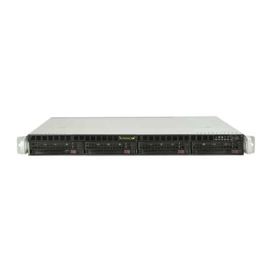
UPER ERVER 5018D-MHR7N4P User's Manual Figure 6-1. Chassis Front View Slim Optical or DVD Drive (optional) Control Panel Hard Drive Bays (4) System Reset Main Power Figure 6-2. Chassis Rear View PCI Slot Power Supply Modules* I/O Ports Control Panel The control panel (located on the front of the chassis) must be connected to the JF1 connector on the serverboard to provide you with system control buttons and status indicators. -
Page 71: System Fans
Proceed to the "DVD-ROM Drive Installation" section in this chapter for instructions. Note that only a "slim" DVD-ROM drive will fit into the 5018D-MHR7N4P. Warning! Enterprise level hard disk drives are recommended for use in Supermicro chassis and servers. For information on recommended HDDs, visit the Supermicro web... -
Page 72: Sata Drive Installation
UPER ERVER 5018D-MHR7N4P User's Manual SATA Drive Installation Mounting a Drive in a Drive Carrier The SATA drives are mounted in drive carriers to simplify their installation and removal from the chassis. These carriers also help promote proper airflow for the system. -
Page 73: Sata Backplane
Chapter 6: Advanced Chassis Setup SATA Backplane The SATA drives plug into a backplane that provides power, drive ID and bus termination. Figure 6-4. Removing a Drive from the Server... - Page 74 UPER ERVER 5018D-MHR7N4P User's Manual DVD-ROM Drive Installation (Optional) The top cover of the chassis must be opened to gain full access to the DVD-ROM drive bay. The 5018D-MHR7N4P accommodates only slim DVD-ROM drives. Side mounting brackets (p/n MCP-220-81502-0N) are needed to mount a slim DVD- ROM drive into the server.
-
Page 75: Power Supply
The Power LED will illuminate and remain on until the failed unit has been replaced. Replace- ment units can be ordered directly from Supermicro. The power supply units have a hot-swap capability, meaning you can replace the failed unit without powering down the system. - Page 76 UPER ERVER 5018D-MHR7N4P User's Manual 4. Carefully insert the new unit into position in the chassis and push it in until fully seated. 5. Reconnect the power cord to the new power supply.
-
Page 77: Chapter 7 Bios
When an option is selected in the left frame, it is highlighted in white. Often a text message will accompany it. (Note: the AMI BIOS has default text messages built in. Supermicro retains the option to include, omit, or change any of these text messages.) The AMI BIOS setup utility uses a key-based navigation system called "hot keys". -
Page 78: How To Start The Setup Utility
Flashing the wrong BIOS can cause irreparable damage to the system. In no event shall Supermicro be liable for direct, indirect, special, incidental, or consequential dam- ages arising from a BIOS update. If you have to update the BIOS, do not shut down or reset the system while the BIOS is updating. - Page 79 Day MM/DD/YY format. The time is entered in HH:MM:SS format. Note: The time is in the 24-hour format. For example, 5:30 P.M. appears as 17:30:00. The following BIOS items will also be displayed: Supermicro X10SDV-7TP4F Version Build Date Memory Information Total Memory This displays the total size of memory available in the system.
-
Page 80: Advanced Setup Configurations
UPER ERVER 5018D-MHR7N4P User's Manual Advanced Setup Configurations Use the arrow keys to select Boot Setup and press <Enter> to access the submenu items. Warning: Take caution when changing the Advanced settings. An incorrect value, a very high DRAM frequency, or an incorrect DRAM timing setting may make the system unstable. - Page 81 Chapter 7: BIOS Wait For 'F1' If Error Use this feature to force the system to wait until the 'F1' key is pressed if an error occurs. The options are Disabled and Enabled. INT19 (Interrupt 19) Trap Response Interrupt 19 is the software interrupt that handles the boot disk function. When this item is set to Immediate, the ROM BIOS of the host adaptors will "capture"...
- Page 82 UPER ERVER 5018D-MHR7N4P User's Manual CPU Configuration The following CPU information will be displayed: • Processor ID • Processor Frequency • Processor Max Ratio • Processor Min Ratio • Microcode Revision • L1 Cache RAM • L2 Cache RAM • L3 Cache Ram •...
- Page 83 Chapter 7: BIOS Execute Disable Bit (Available if supported by the OS & the CPU) Select Enabled to enable the Execute-Disable Bit which will allow the processor to designate areas in the system memory where an application code can execute and where it cannot, thus preventing a worm or a virus from flooding illegal codes to overwhelm the processor or damage the system during an attack.
- Page 84 UPER ERVER 5018D-MHR7N4P User's Manual Note: If a change is made to this setting, you will need to reboot the system for the change to take effect. Refer to Intel’s website for detailed information. Advanced Power Management Configuration This section is used to configure the following CPU Power Management settings. EIST (P-States) EIST (Enhanced Intel SpeedStep Technology) allows the system to automatically adjust processor voltage and core frequency to reduce power consumption and...
- Page 85 Chapter 7: BIOS CPU HWPM State Control Enable CPU HWPM Select Enable for better CPU energy performance. The options are Disable, HWPM NATIVE MODE, and HWPM OOB MODE. Enable CPU Autonomous Cstate Use this feature to enable CPU Autonomous C State, which converts HALT instructions to Mwait.
- Page 86 UPER ERVER 5018D-MHR7N4P User's Manual CPU T State Control ACPI (Advanced Configuration Power Interface) T-States Select Enable to support CPU throttling by the operating system to reduce power consumption. The options are Disable and Enable. CPU Advanced PM Turning ...
- Page 87 Chapter 7: BIOS Energy Efficient Turbo Use this feature to enable energy efficient turbo mode. The options are En- able and Disable. DRAM RAPL Configuration Override BW_LIMIT_TF This feature allows the user to turn off the "Override BW_LIMIT_TF (Time Frame)"...
- Page 88 UPER ERVER 5018D-MHR7N4P User's Manual CPU SLOT 6 PCI-E 3.0 X8 This item configures the link speed of the PCI-E port specified by the user. The options are Gen 1 (Generation 1) (2.5 GT/s), Gen 2 (Generation 2) (5 GT/s), and Gen 3 (Generation 3) (8 GT/s).
- Page 89 Chapter 7: BIOS Memory Configuration Enforce POR Select Enable to enforce POR restrictions on DDR4 frequency and voltage programming. The options are Enabled and Disabled. Memory Frequency Use this feature to set the maximum memory frequency for onboard memory modules. The options are Auto, 1333, 1400, 1600, 1800, 1867, 2000, 2133, 2200, 2400, 2600, 2667, 2800, 2993, 3000, 3200, and Reserved (Do not select Reserved).
- Page 90 UPER ERVER 5018D-MHR7N4P User's Manual Memory RAS (Reliability_Availability_Serviceability) Configuration Use this submenu to configure the following Memory RAS settings. Patrol Scrub Patrol Scrubbing is a process that allows the CPU to correct correctable memory errors detected on a memory module and send the correction to the requestor (the original source).
- Page 91 Chapter 7: BIOS XHCI Hand-Off This is a work-around solution for operating systems that do not support XHCI (Ex- tensible Host Controller Interface) hand-off. The XHCI ownership change should be claimed by the XHCI driver. The settings are Enabled and Disabled. EHCI Hand-Off This item is for the Operating Systems that do not support Enhanced Host Controller Interface (EHCI) hand-off.
- Page 92 UPER ERVER 5018D-MHR7N4P User's Manual *If the item "Configure SATA as" is set to AHCI, the following items will display: SATA Frozen Use this item to enable the HDD Security Frozen Mode. The options are Disabled and Enabled. SATA AHCI LPM Use this feature to enable the Link Power Management for SATA AHCI.
- Page 93 Chapter 7: BIOS *If the item "Configure SATA as" is set to IDE, the following items will display: SATA Frozen Use this item to enable the HDD Security Frozen Mode. The options are Dis- abled and Enabled. Port 0 ~ Port 5 SATA Device Type (Available when a SATA port is detected) Use this item to specify if the SATA port specified by the user should be con- nected to a Solid State drive or a Hard Disk Drive.
- Page 94 UPER ERVER 5018D-MHR7N4P User's Manual Select Enabled to allow a PCI device to generate a PERR/SERR number for a PCI Bus Signal Error Event. The options are Enabled and Disabled. Above 4G Decoding (Available if the system supports 64-bit PCI decoding) Select Enabled to decode a PCI device that supports 64-bit in the space above 4G Address.
- Page 95 Chapter 7: BIOS PCI-E 2.0 X1 OPROM Use this feature to select which firmware type to be loaded for the add-on card in this slot. The options are Disabled, Legacy, and EFI. Onboard SAS Option ROM Use this feature to select which firmware to be loaded for the onboard SAS Option ROM.
- Page 96 UPER ERVER 5018D-MHR7N4P User's Manual PXE boot wait time Use this option to specify the wait time to press the ESC key to abort the PXE boot. Press "+" or "-" on your keyboard to change the value. The default setting is 0. Media detect count Use this option to specify the number of times media will be checked.
- Page 97 Chapter 7: BIOS COM1 Console Redirection Settings This feature allows the user to specify how the host computer will exchange data with the client computer, which is the remote computer used by the user. Terminal Type This feature allows the user to select the target terminal emulation type for Console Redirection.
- Page 98 UPER ERVER 5018D-MHR7N4P User's Manual VT-UTF8 Combo Key Support Select Enabled to enable VT-UTF8 Combination Key support for ANSI/VT100 ter- minals. The options are Disabled and Enabled. Recorder Mode Select Enabled to capture the data displayed on a terminal and send it as text mes- sages to a remote server.
- Page 99 Chapter 7: BIOS function key support. Select ANSI to use the Extended ASCII Character Set. Select VT-UTF8 to use UTF8 encoding to map Unicode characters into one or more bytes. The options are ANSI, VT100, VT100+, and VT-UTF8. Bits Per second Use this feature to set the transmission speed for a serial port used in Console Redirection.
- Page 100 UPER ERVER 5018D-MHR7N4P User's Manual Resolution 100x31 Select Enabled for extended-terminal resolution support. The options are Disabled and Enabled. Legacy OS Redirection Resolution Use this feature to select the number of rows and columns used in Console Redi- rection for legacy OS support. The options are 80x24 and 80x25. Putty KeyPad This feature selects Function Keys and KeyPad settings for Putty, which is a terminal emulator designed for the Windows OS.
- Page 101 Chapter 7: BIOS function key support. Select ANSI to use the extended ASCII character set. Select VT-UTF8 to use UTF8 encoding to map Unicode characters into one or more bytes. The options are ANSI, VT100, VT100+, and VT-UTF8. Bits Per Second This item sets the transmission speed for a serial port used in Console Redirec- tion.
- Page 102 UPER ERVER 5018D-MHR7N4P User's Manual This feature Enables the Windows Hardware Error Architecture (WHEA) support for the Windows 2008 (or a later version) operating system. The options are Disabled and Enabled. High Precision Event Timer Select Enabled to activate the High Performance Event Timer (HPET) that produces periodic interrupts at a much higher frequency than a Real-time Clock (RTC) does in synchronizing multimedia streams, providing smooth playback and reducing the de- pendency on other timestamp calculation devices, such as an x86 RDTSC Instruc-...
- Page 103 Chapter 7: BIOS TPM Enabled Status TPM Active Status TPM Owner Status TXT Support Intel TXT (Trusted Execution Technology) helps protect against software-based at- tacks and ensures protection, confidentiality and integrity of data stored or created on the system. Use this feature to enable or disable TXT Support. The options are Disabled and Enabled.
-
Page 104: Event Logs
UPER ERVER 5018D-MHR7N4P User's Manual Event Logs Use this feature to configure Event Log settings. Change SMBIOS Event Log Settings Enabling/Disabling Options SMBIOS Event Log Change this item to enable or disable all features of the SMBIOS Event Logging during system boot. The options are Enabled and Disabled. Runtime Error Logging Support Select Enabled to support Runtime Error Logging. - Page 105 Chapter 7: BIOS PCI-Ex (PCI-Express) Error Enable Select Yes for the BIOS to correct errors occurred in the PCI-E slots. The options are Yes and No. Erasing Settings Erase Event Log If No is selected, data stored in the event log will not be erased. Select Yes, Next Reset, data in the event log will be erased upon next system reboot.
-
Page 106: Ipmi
UPER ERVER 5018D-MHR7N4P User's Manual IPMI Use this feature to configure Intelligent Platform Management Interface (IPMI) settings. BMC Firmware Revision This item indicates the IPMI firmware revision used in your system. IPMI STATUS (Baseboard Management Controller) This item indicates the status of the IPMI firmware installed in your system. System Event Log ... - Page 107 Chapter 7: BIOS When SEL is Full This feature allows the user to decide what the BIOS should do when the system event log is full. Select Erase Immediately to erase all events in the log when the system event log is full. The options are Do Nothing and Erase Immediately. Note: After making changes on a setting, be sure to reboot the system for the changes to take effect.
- Page 108 When Disabled, the system powers on quickly by removing BIOS support for extended IPMI features. The Disable option is for applications that require faster power on time wthout using Supermicro Update Manager (SUM) or extended IPMI features. The BMC network configuration in the BIOS setup is also invalid when IPMI Function Support is disabled.
-
Page 109: Security Settings
Chapter 7: BIOS Security Settings This menu allows the user to configure the following security settings for the system. Password Check Select Setup for the system to check for a password at Setup. Select Always for the system to check for a password at bootup or upon entering the BIOS Setup utility. The options are Setup and Always. - Page 110 UPER ERVER 5018D-MHR7N4P User's Manual Secure Boot Use this item to enable secure boot. The options are Disabled and Enabled. Secure Boot Mode Use this item to select the secure boot mode. The options are Standard and Custom. Key Management This submenu allows the user to configure the following Key Management settings.
- Page 111 Chapter 7: BIOS Authorized Signatures Set New Key Select Yes to load the database from the manufacturer's defaults. Select No to load the DB from a file. The options are Yes and No. Append Key Select Yes to add the database from the manufacturer's defaults to the existing DB. Select No to load the DB from a file.
-
Page 112: Boot Settings
UPER ERVER 5018D-MHR7N4P User's Manual Boot Settings Use this feature to configure Boot Settings: Boot Mode Select Use this item to select the type of device that the system is going to boot from. The options are Legacy, UEFI, and Dual. The default setting is Dual. Fixed Boot Order Priorities This option prioritizes the order of bootable devices that the system to boot from. - Page 113 Chapter 7: BIOS • Dual Boot Order #9 • Dual Boot Order #10 • Dual Boot Order #11 • Dual Boot Order #12 • Dual Boot Order #13 • Dual Boot Order #14 • Dual Boot Order #15 Delete Boot Option Use this feature to remove a pre-defined boot device from which the system will boot during startup.
-
Page 114: Save & Exit
UPER ERVER 5018D-MHR7N4P User's Manual Save & Exit Select the Exit tab from the BIOS setup utility screen to enter the Exit BIOS Setup screen. Discard Changes and Exit Select this option to quit the BIOS Setup without making any permanent changes to the system configuration, and reboot the computer. - Page 115 Chapter 7: BIOS Restore Defaults To set this feature, select Restore Defaults from the Save & Exit menu and press <Enter>. These are factory settings designed for maximum system stability, but not for maximum performance. Save As User Defaults To set this feature, select Save as User Defaults from the Exit menu and press <En- ter>.
- Page 116 UPER ERVER 5018D-MHR7N4P User's Manual Notes 7-40...
-
Page 117: Appendix A Bios Error Beep Codes
Appendix A: BIOS Error Beep Codes Appendix A BIOS Error Beep Codes During the POST (Power-On Self-Test) routines, which are performed upon each system boot, errors may occur. Non-fatal errors are those which, in most cases, allow the system to continue to boot. - Page 118 UPER ERVER 5018D-MHR7N4P User's Manual Notes...
-
Page 119: Appendix B System Specifications
Appendix B: System Specifications Appendix B System Specifications Processor Single Intel® Xeon/Pentium® D-1537 SoC embedded processor (SoC = System on a Chip BIOS 128 Mb AMI® SPI Flash EEPROM Memory Capacity Four SO-DIMM slots that can support up to 128 GB of ECC RDIMM (Registered DIMM) or 64 GB of ECC/non-ECC UDIMM (Unregistered DIMM) DDR4- 1866/1600 memory Note: see Section 5-5 for details. - Page 120 UPER ERVER 5018D-MHR7N4P User's Manual System Input Requirements AC Input Voltage: 100 - 240V AC auto-range Rated Input Current: 6A (100V) to 3A (240V) Rated Input Frequency: 50 to 60 Hz Power Supply Rated Output Power: 400W (Part# PWS-407P-1R) Rated Output Voltages: +5V (25A), +3.3V (25A), +12V (33A), +5Vsb (3A), -12V (0.6A) Operating Environment Operating Temperature: 10º...
- Page 121 Appendix B: System Specifications Notes...
- Page 122 ERVER 5018D-MHR7N4P User's Manual (continued from front) The products sold by Supermicro are not intended for and will not be used in life support systems, medical equipment, nuclear facilities or systems, aircraft, aircraft devices, aircraft/emergency com- munication devices or other critical systems whose failure to perform be reasonably expected to result in significant injury or loss of life or catastrophic property damage.
-
Page 123: Appendix C Uefi Bios Recovery Instructions
Flashing the wrong BIOS can cause irreparable damage to the system. In no event shall Supermicro be liable for direct, indirect, special, incidental, or consequential damages arising from a BIOS update. If you need to update the BIOS, do not shut down or reset the system while the BIOS is updating to avoid possible boot failure. - Page 124 ERVER 5018D-MHR7N4P User's Manual Note: If you cannot locate the "Super.ROM" file in your driver disk, visit our website at www.supermicro.com to download the BIOS image to a USB flash device and rename it "Super ROM". 2. Insert the USB device that contains the new BIOS image ("Super.ROM") into your USB drive and power on the system 3.
- Page 125 Appendix C: UEFI BIOS Recovery 6. After the process has completed, press any key to reboot the system. 7. Using a different system, extract the BIOS package into a bootable USB flash drive. 8. When the DOS prompt appears, enter AMI.BAT BIOSname.###. Note: Do not interrupt this process until BIOS flashing has completed.
- Page 126 UPER ERVER 5018D-MHR7N4P User's Manual 9. After receiving the message that the BIOS update is complete, unplug the AC power cable from the power supply to clear CMOS, then plug the AC power cable in the power supply again to power on the system. 10.
Need help?
Do you have a question about the SUPERSERVER 5018D-MHR7N4P and is the answer not in the manual?
Questions and answers