
Subscribe to Our Youtube Channel
Related Manuals for Vista VP-HDA30-PM


Summary of Contents for Vista VP-HDA30-PM
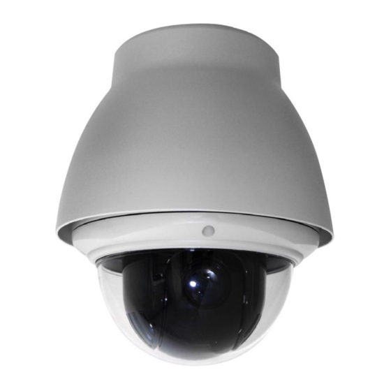
- Page 1 Installation Manual VP-HDA30-PM Please read this manual thoroughly before use and keep it handy for future reference.
- Page 3 Norbain SD, 210 Wharfedale Road, Winnersh Triangle, Wokingham, Berkshire RG41 5TP, England. UK +44 (0) 118 912 5000 / Vista Technical Support +44 (0) 118 912 5125 Note: You should be at the equipment and ready with details before calling Technical Support.
-
Page 4: Important Safety Instructions
CAUTION RISK OF ELECTRIC SHOCK DO NOT OPEN CAUTION: TO REDUCE THE RISK OF ELECTRIC SHOCK, DO NOT REMOVE COVER (OR BACK) NO USER-SERVICEABLE PARTS INSIDE. REFER SERVICING TO QUALIFIED SERVICE PERSONNEL. IMPORTANT SAFETY INSTRUCTIONS Read these instructions. Keep these instructions. Heed all warnings. -
Page 5: Table Of Contents
Table of Contents Chapter 1 — Introduction ....................6 1.1 Features ..........................6 Chapter 2 — Installation and Configuration ..............7 2.1 Package Contents ....................... 7 2.2 Mounting the Camera ......................8 2.3 Installation – PTZ Camera Remove for Maintenance ............9 2.4 Basic Configuration of Dome Camera System .............. -
Page 6: Chapter 1 - Introduction
Up to 3999 selectable camera addresses Function Run menu using DVR without function key (Pattern, Scan …) Hikvision-C, Pelco-C or Fastrax-C coaxial protocols Auto sensing RS485 telemetry supporting: Vista-485, Pelco P & D protocols 12VDC or 24VAC for Camera 24VAC for Heater & Fan IP66 and built to IK10 (EN 62262) Use clause 2.5 of IEC60950-1/UL60950-1 or Certified/Listed Class 2 power source only. -
Page 7: Chapter 2 - Installation And Configuration
Chapter 2 — Installation and Configuration 2.1 Package Contents The package contains the following. * Dome Camera * Instruction Manual (This Document) * Accessory Kit & Connector 1) Torx wrench 2) 2-Pin Terminal Block 3) 3-Pin Terminal Block 4) 4-Pin Terminal Block 5) 5-Pin Terminal Block * Install Adaptor... -
Page 8: Mounting The Camera
2.2 Mounting the Camera Please see the Vista Solution guide for available bracketry and mounting options. The wall or ceiling mount must be attached to a structural object such as hard wood, concrete that will support the weight of the mount and dome camera. -
Page 9: Installation - Ptz Camera Remove For Maintenance
2.3 Installation – PTZ Camera Remove for Maintenance In order to perform maintenance or change hardware setting, remove lower dome cover first and unlock the camera assembly by turning in the direction indicated by the arrows in the figure below to remove the PTZ camera. The ceiling mounting plate must be attached to a structural object such as concrete that will support the weight of the mount and dome camera. -
Page 10: Basic Configuration Of Dome Camera System
2.4 Basic Configuration of Dome Camera System Connector Wire Color Description 24VAC or 12VDC+ 3-pin terminal block WHITE 24VAC or 12VDC- PINK Heater & Fan (24VAC) 3-pin terminal block BROWN Heater & Fan (24VAC) GREEN RS-485+ 2-pin terminal block BLUE RS-485- GRAY ALARM INPUT 1... -
Page 11: Setting Dome Camera Address (Id)
THE BUBBLE IS THE PRIMARY SEAL. 2.5 Setting Dome Camera Address (ID) To prevent damage, each dome camera must have a unique address (ID). The factory default setting is 1. Refer to ‘3.11 Dome Communication’ section for detailed information. 2.6 Setting Dome Camera Video Type, Termination & Coaxial Protocol You can set video type with D1 and termination with D2 in SW1. -
Page 12: Connections
2.7 Connections • Connecting to the RS-485 The dome camera can be controlled remotely by an external device or control system, such as a control keyboard, using RS-485 half-duplex serial communications signals. • Connecting HD-TVI/AHD Output connector Connect the HD-TVI/AHD output (BNC) connector to the monitor or video input. •... -
Page 13: Getting Started
2.8 Getting Started Once installed apply power to the dome camera. The dome camera will start a configuration sequence. STATUS of FUNCTION TITLE AF AE FOCUS and AE INFORMATION EMPTY DATA DISPLAY ALARM:1 ALARM DISPLAY CAMERA TITLE & ID DOMEID:0001 360.0 090.0 PAN &... -
Page 14: Chapter 3 - Program And Operation
No. + CAM keys from your controlling device (keyboard/DVR). Example: Pressing 1 & CAMERA keys from a Vista VKBD4 keyboard sequentially, will select camera 1. The selected dome camera ID will be displayed on the LCD display of the keyboard controller. -
Page 15: Auto Scan Setup
3.4 Auto Scan Setup Allows the camera to be set up to move automatically between 2 programmed locations, the Auto Scan can be recalled from the controlling device using the AUX6 command from a VKBD4. AUTO SCAN SETUP NUMBER : 01 TITLE : A01 MODE... - Page 16 2. Select ‘MODE’ - adjust with (Tele/Wide) 3. Select ‘SPEED’ - adjust with (Tele/Wide) 4. ‘START ANGLE’ Use the Joystick to move cursor to START ANGLE Press the (IO/FN) key ‘CONTROL’ is displayed. Move the camera to the desired location and the zoom position. Press the (IC/FF) and ‘CONTROL’...
-
Page 17: Preset Setup
3.5 Preset Setup Up to 240 Presets may be programmed. Presets can be recalled No. + PRESET. Presets are very powerful and allow you to set the camera parameters and even a motion alarm for each preset. There are eight pages of Preset menu. Each page has 30 Presets. The pages can be scrolled by moving the Joystick to the NEXT PAGE and (Tele/Wide). - Page 18 Select ‘MOTION SETUP’ and move Joystick to the right, the ‘MOTION SETUP’ menu is displayed. MOTION SETUP SENSITIVITY: 10 RESOLUTION : 02 POSITION : ALL DELAY : 00 SEC OUTPUT : OFF HOLD TIME : 03 SEC EXIT(ESC TO EXIT) 00 –...
- Page 19 NOTE: AUTO in D/N MODE option is not applied in ‘MANUAL’ mode of AE Setup. Select ‘ADDITIONAL AE’ and move Joystick to the right, the ‘ADDITIONAL AE SETUP’ menu is displayed. ADDITIONAL AE SETUP : OFF : OFF WDR WEIGHT : -- : OFF : OFF...
-
Page 20: Quick Setting A Preset
3.6 Quick Setting a Preset This can be achieved after selecting the desired scene e.g. with VKBD4 by pressing FUNCTION (Fn) then the No. (1 to 240) then PRESET key sequentially. The current view will be stored to the selected Preset number. If the Preset number is not empty, an ‘OVER WRITE’... - Page 21 3. To scroll to a stored Preset, adjust with (Tele/Wide) then the stored Preset number displays. 4. To select functions other than Preset, press the (IO/FN) key to scroll for Tour, Pattern or Auto Scan respectively (if you wish to remove a Preset or Function from a Tour keep pushing (IO/FN) until ‘---‘...
-
Page 22: Pattern Setup (Learn Tour)
3.8 Pattern Setup (Learn Tour) The Pattern feature records up to a maximum of 500 seconds of user control. Up to 8 Patterns can be stored, inserted into a Tour and played back by pressing the No. + Learn keys sequentially. PATTERN SETUP (CTRL KEY) TITLE... -
Page 23: Privacy Zone Setup
3.9 Privacy Zone Setup Up to 16 Privacy Zones may be programmed. There are four pages of Privacy Zones menu. Each page has 4 Privacy Zones. The pages can be scrolled by moving the Joystick to the NEXT PAGE and (Tele/Wide). PRIVACY ZONE SETUP (CTRL KEY) METHOD... -
Page 24: Camera Setup
3.10 Camera Setup Use the Joystick to move the cursor, right to select sub menu (if applicable) and (Tele/Wide) to adjust. To save changes highlight ‘SAVE AND EXIT’ and move Joystick right. Joystick left exits without saving. CAMERA SETUP FOCUS CONTROL WB CONTROL AE CONTROL CAMERA CONTROL... - Page 25 • WB SETUP (White Balance) WB SETUP MODE : AUTO R GAIN : --- B GAIN : --- SAVE AND EXIT(ESC TO CANCEL) MODE AUTO, MANUAL, INCANDESCENT, FLUORESCENT, OUTDOOR Automatically computes the picture’s white balance using colour AUTO information from the entire screen. INCANDESCENT Incandescent white balance mode FLUORESCENT...
- Page 26 Permanent monochrome mode COLOUR Permanent colour mode These 3 settings can be temporarily overridden for a 60 second period via the day/night command function from the VKBD4. NOTE: AUTO in D/N MODE option is not applied in ‘MANUAL’ mode of AE Setup. ADDITIONAL AE SETUP ADDITIONAL AE SETUP : OFF...
-
Page 27: Dome Communication
DOME COMMUNICATION DOME ID : 0001 PROTOCOL : AUTO BAUDRATE : 9600 PARITY : NONE SAVE AND EXIT(ESC TO CANCEL) 1 – 3999 DOME ID PROTOCOL AUTO, F2/F2E, PELCO-PD, VISTA BAUDRATE 2400, 4800, 9600, 19200, 38400 bps PARITY NONE, EVEN, ODD... -
Page 28: Alarm Setup
3.12 Alarm Setup Use the Joystick to move the cursor and (Tele/Wide) to adjust. To save changes highlight ‘SAVE AND EXIT’ and move Joystick right. Joystick left exits without saving. ALARM SETUP (CTRL KEY) NO PRI FUN IN LATCH 001 NO OUT1 01 --- OFF --- OFF... -
Page 29: Configuration Menu (Dome Setup)
3.13 Configuration Menu (Dome Setup) Use the Joystick to move the cursor, right to select sub menu (if applicable) and (Tele/Wide) to adjust. To save changes highlight ‘SAVE AND EXIT’ and move Joystick right. Joystick left exits without saving. CONFIGURATION MENU HOME FUNCTION SETUP VIEW ANGLE SETUP ORIGIN OFFSET... - Page 30 • VIEW ANGLE SETUP Use the Joystick to move the cursor and (Tele/Wide) to adjust. To save changes highlight ‘SAVE AND EXIT’ and move Joystick right. Joystick left exits without saving. VIEW ANGLE SETUP PANNING RANGE FLIP : 90 TILT ANGLE LIMIT : 00 SAVE AND EXIT(ESC TO CANCEL) FLIP...
- Page 31 • OFFSET SETUP (Origin Offset) Use the Joystick to move the cursor and (Tele/Wide) to adjust. To save changes highlight ‘SAVE AND EXIT’ and move Joystick right. Joystick left exits without saving. OFFSET SETUP (CTRL KEY) PAN OFFSET : 000.0 TILT OFFSET : 000.0 ENABLE...
- Page 32 • OSD DISPLAY SETUP Use the Joystick to move the cursor, right to select sub menu (if applicable) and (Tele/Wide) to adjust. To save changes highlight ‘SAVE AND EXIT’ and move Joystick right. Joystick left exits without saving. OSD DISPLAY SETUP LANQUAGE : ENGLISH TITLE...
- Page 33 MOTOR SETUP Use the Joystick to move the cursor and (Tele/Wide) to adjust. To save changes highlight ‘SAVE AND EXIT’ and move Joystick right. Joystick left exits without saving. MOTOR SETUP PROPORTIONAL P/T P/T MODE : NORMAL SLOW PAN MAX SLOW TILT MAX NORMAL PAN MAX NORMAL TILT MAX...
- Page 34 ORIGIN CHECK If the presets or privacy zones appear to have moved, carry out an origin check as this will be zero the camera module position. Use the Joystick to move the cursor and right or (IO/FN) to accept selection. ORIGIN CHECK ARE YOU SURE ? CANCEL...
- Page 35 Cont/… ALARM OUT SETUP OUT1 : ALARM OUT2 : 1 MIN EXIT(ESC TO EXIT) (IO/FN) to operate alarm out during the setting time only. • SYSTEM INFORMATION SYSTEM INFORMATION CAMERA TYPE : xxxx-Vx.xx H/W VERSION : Vx.xx-xxxx ROM VERSION : Vx.xxxxxx PROTOCOL : xxxx BAUDRATE...
-
Page 36: Appendix A - Specifications
Appendix A — Specifications Model VP-HDA30-PM IMAGE Lens 4.3mm ~ 129.0mm (F1.6 – 4.7) Angle of View 65.1° (H) ~ 2.23° (H) Image Sensor Type 1/2.8" SONY STARVIS CMOS sensor Pixels 1945 (H) x 1097 (V) Color : 0.35 Lux @ 50IRE Min. - Page 37 Operating Humidity 0 ~ 90%RH (Non-condensing) Operating Temperature -50 C ~ 65 C Camera 12VDC, 24VAC Power Supply Heater & Fan 24VAC Camera 1.0A (12.0W) @ 12VDC, 24VAC Power Consumption Heater & Fan 2.2A (50.0W) @ 24VAC Dimensions See dimension drawing Net Weight Approx.
-
Page 38: Appendix B - Troubleshooting
Appendix B — Troubleshooting If problems occur, verify the installation of the camera with the instructions in this manual and with other operating equipment. Isolate the problem to the specific piece of equipment in the system and refer to the equipment manual for further information. Problem Possible Solution Verify that power is connected to all pieces of equipment... - Page 40 Vista 210 Wharfedale Road Winnersh Triangle Wokingham Berkshire. RG41 5TP (Subject to change without notice) Version 1.0 50304031A...
Need help?
Do you have a question about the VP-HDA30-PM and is the answer not in the manual?
Questions and answers