
Subscribe to Our Youtube Channel
Related Manuals for Vista VPL7-WP-SM


Summary of Contents for Vista VPL7-WP-SM
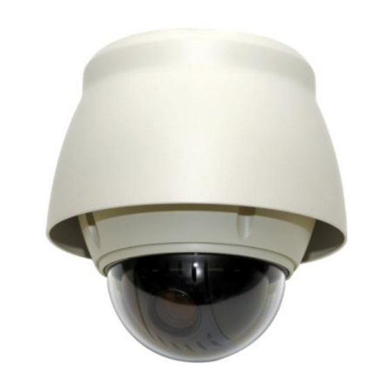
- Page 1 VPL7 Installation Manual Set up and user manual for the VPL7-WP-SM VPL7-WP-PM Fully functional dome camera Installation and user guide...
-
Page 2: Explanation Of Graphical Symbols
WARNING TO REDUCE THE RISK OF FIRE OR ELECTRIC SHOCK, DO NOT EXPOSE THIS PRODUCT TO RAIN OR MOISTURE. DO NOT INSERT ANY METALLIC OBJECTS THROUGH THE VENTILATION GRILLS OR OTHER OPENINGS ON THE EQUIPMENT. CAUTION EXPLANATION OF GRAPHICAL SYMBOLS The lightning flash with arrowhead symbol, within an equilateral triangle, is intended to alert the user to the presence of uninsulated “dangerous voltage”... - Page 3 Before You Begin Read these instructions before installing or operating this product. Note: It is recommended that the camera is installed by personnel with a basic knowledge of CCTV systems and componentry, along with a knowledge of electrical wiring and low-voltage electrical connections.
-
Page 4: Important Safety Instructions
IMPORTANT SAFETY INSTRUCTIONS 1. Read & keep these instructions. 2. Heed all warnings & follow all instructions. 3. Protect the power connections from moisture. 4. Clean only with dry cloth. 5. Do not block any ventilation openings. Install in accordance with the manufacturer’s instructions. -
Page 5: Table Of Contents
3.10 Configuration Menu (Dome Setup) ................22 Appendix A — Specifications ....................30 Appendix B — Troubleshooting..................... 33 Appendix C — Glossary ......................33 Appendix D — Dome Camera ID settings (17 - 255) ............36 Appendix E — Surface Mounting the VPL7-WP-SM ............42... -
Page 6: Chapter 1 - Introduction
Image flip – allows the camera to be mounted on the floor/ground for under vehicle surveillance Up to 255 selectable camera addresses Auto sensing RS485 telemetry supporting: Vista-485, Pelco P & D protocols Co-axial control with Vista-FSK Multi-language OSD: English, French, German, Italian, Spanish, Polish & Portuguese... -
Page 7: Chapter 2 - Installation And Configuration
The cameras are housed in compact housing, constructed of aluminum, steel and plastic, designed for wall, ceiling and pole mounting - the VPL7-WP-SM can also be floor mounted. Bracketry is not included, so please discuss with sales regarding mounting options and bracketry required to fulfill this. -
Page 8: Installation
Alarms: Alarm cable is suitable or Cat 5 cable for longer distances up to 380m. For FSK control (Coaxial telemetry – Vista only), the data cable is not required. Pure copper coaxial cable and crimp-on BNC connectors are recommended. Do not use copper-coated steel... -
Page 9: Connections
2.2 Connections • Connecting to the RS485 The dome camera can be controlled remotely by an external device or control system, such as a control keyboard, using RS485 half-duplex serial communications signals. • Connecting Video Output connector Connect the video output (BNC) connector to the monitor or video input. •... -
Page 10: Basic Configuration Of Dome Camera System
2.3 Basic Configuration of Dome Camera System NOTE: Only the VPL7-WP-PM has this connection (Pink & Brown) and is for the Heater and Fan Figure 2– Basic Installation Diagram... -
Page 11: Setting Dome Camera Termination
VPL7-WP-SM VPL7-WP-PM Figure 3 – Layout of DIP Switches NOTE: Open the switch cover (image ‘a’) to make any changes to the setting of DIP switches. Primary Seal This cover is a and as such needs to be refitted correctly once any DIP switch Failure to do this could allow moisture ingress, which may settings have been made. -
Page 12: Setting Dome Camera Address (Id)
2.5 Setting Dome Camera Address (ID) To ensure effective telemetry control of the dome, each dome camera must have a unique address (ID). When installing multiple dome cameras using a Multiplexer, DVR or Matrix, it is suggested that the dome camera address (ID) matches the camera input. The factory default setting is 1. -
Page 13: Setting Dome Camera Protocol
RS485 protocol commands on the data line, then use the DIP switch settings below to force the camera to the required protocol. If you are not using a Vista Keyboard or DVR for the telemetry control then you may need to refer to the user manual for that product. -
Page 14: Getting Started
No. + CAM keys from your controlling device (keyboard/DVR). Example: Pressing 1 & CAMERA keys from a Vista VKBD4 keyboard sequentially, will select camera 1. The selected dome camera ID will be displayed on the LCD display of... -
Page 15: How To Control The On-Screen Menu
Please be aware that whilst the commands in BOLD in the table below are generic for most keyboards, DVR’s and popular protocols, if you are not using a Vista controller and Protocol then you may need to refer to the user manual for that controlling device to generate the required command. -
Page 16: Chapter 3 - Program And Operation
Chapter 3 — Program and Operation 3.1 Auto Scan Setup Allows the Dome to be set up to move automatically between 2 programmed locations, the Auto Scan can be recalled from the controlling device using the AUX6 command from a VKBD4. AUTO SCAN SETUP NUMBER : 01... -
Page 17: Preset Setup
2. Select ‘MODE’ - adjust with (Tele/Wide) 3. Select ‘SPEED’ - adjust with (Tele/Wide) 4. ‘START ANGLE’ Use the Joystick to move cursor to START ANGLE Press the (IO/FN) key ‘CONTROL’ is displayed. Move the camera to the desired location and the zoom position. Press the (IC/FF) and ‘CONTROL’... - Page 18 1. Use the Joystick to move the cursor to the preset position you wish to add/adjust. 2. After selecting a preset position (blank or already populated), press the (IO/FN) key ‘CONTROL’ is displayed. Move to the desired location and zoom position then press the (IC/FF) key then ‘CONTROL’...
- Page 19 Select ‘AE SETUP’ and move the Joystick to the right, the AE setup menu is displayed. AE SETUP MODE : MANUAL DSS LIMIT : OFF GAIN : MIN BRIGHT : 024 SHUTTER : 1/50 FLICKERLESS : --- BACK LIGHT : OFF : --- WDR LEVEL : ---...
-
Page 20: Quick Setting A Preset
3.3 Quick Setting a Preset This can be achieved after selecting the desired scene e.g. with VKBD4 by pressing FUNCTION (Fn) then the No. (1 to 240) then PRESET key sequentially. The current view will be stored to the selected Preset number. If the Preset number is not empty, an ‘OVER WRITE’... -
Page 21: Pattern Setup (Learn Tour)
6. Select ‘TITLE’ – this can be changed one of two ways: Moving the Joystick left and right to select the cursor location and (Tele/Wide) to change the character Use the Joystick to move the cursor to the alpha numeric character table displayed and select the required character with the (IO/FN) keys. -
Page 22: Alarm Setup
3.6 Alarm Setup Use the Joystick to move the cursor and (Tele/Wide) to adjust. To save changes highlight ‘SAVE AND EXIT’ and move Joystick right. Joystick left exits without saving. ALARM SETUP PRI FUN IN HLD LATCH 001 NO --- OFF OFF --- OFF OFF --- OFF OFF DWELL... -
Page 23: Privacy Zone Setup
3. Select ‘START ANGLE’. Press the (IO/FN) key, then ‘CONTROL’ is displayed. Move to the desired position. Press the (IC/FF) key then ‘CONTROL’ disappears. To adjust at the 0.1 degree interval, twist the Joystick at the pan field and the tilt field. 4. -
Page 24: Camera Setup
3.9 Camera Setup Use the Joystick to move the cursor, right to select sub menu (if applicable) and (Tele/Wide) to adjust. To save changes highlight ‘SAVE AND EXIT’ and move Joystick right. Joystick left exits without saving. CAMERA SETUP FOCUS CONTROL WB CONTROL AE CONTROL DNR CONTROL... - Page 25 • WB Set up (White Balance) Use the Joystick to move the cursor and (Tele/Wide) to adjust. To save changes highlight ‘SAVE AND EXIT’ and move Joystick right. Joystick left exits without saving. WB SETUP MODE : AWB R GAIN : --- B GAIN : ---...
- Page 26 OFF / ON (NOTE: When WDR is ON, BACKLIGHT will be disabled) WDR LEVEL LOW / MIDLOW / MID / MIDHIGH / HIGH D/N MODE AUTO / B/W / COLOUR The D/N mode option removes the IR cut filter of the camera and makes the camera sensitive to infrared illumination.
-
Page 27: Configuration Menu (Dome Setup)
3.10 Configuration Menu (Dome Setup) Use the Joystick to move the cursor, right to select sub menu (if applicable) and (Tele/Wide) to adjust. To save changes highlight ‘SAVE AND EXIT’ and move Joystick right. Joystick left exits without saving. CONFIGURATION MENU LANGUAGE : ENGLISH HOME FUNCTION SETUP... - Page 28 • OSD DISPLAY Setup Use the Joystick to move the cursor, right to select sub menu (if applicable) and (Tele/Wide) to adjust. To save changes highlight ‘SAVE AND EXIT’ and move Joystick right. Joystick left exits without saving. OSD DISPLAY SETUP CAMERA TITLE : DOMEID VIEW DIRECTION...
- Page 29 • VIEW ANGLE Setup Use the Joystick to move the cursor and (Tele/Wide) to adjust. To save changes highlight ‘SAVE AND EXIT’ and move Joystick right. Joystick left exits without saving. VIEW ANGLE SETUP PANNING RANGE FLIP : 90 TILT LIMIT : OFF LIMIT ANGLE : ---...
- Page 30 ON: When this is on, the range of the tilt angle is limited to 10 - 170 This prevents the camera from seeing inside the housing/edge of the bubble which can cause focus / hunting issues. LIMIT ANGLE: OFF / ON When ON, the camera module tilts down by 10 , this can then be adjusted upwards in increments of 1 to fine tune / maximize the tilt angle without the camera seeing inside the housing.
- Page 31 PRESET FOCUS DEFAULT Use the Joystick to move the cursor and (Tele/Wide) to adjust. To save changes highlight ‘SAVE AND EXIT’ and move Joystick right. Joystick left exits without saving. This menu set the default mode of the focus when you save the Preset. PRESET FOCUS DEFAULT FOCUS : AUTO...
- Page 32 • SYSTEM MENU Use the Joystick to move the cursor, right to select sub menu (if applicable) and (Tele/Wide) to adjust. To save changes highlight ‘SAVE AND EXIT’ and move Joystick right. Joystick left exits without saving. SYSTEM MENU MOTOR SETUP PASSWORD EDIT ORIGIN CHECK WHITE DEFECT COMPENSATION...
- Page 33 PASSWORD EDIT SETUP Use the Joystick to move the cursor and (IO/FN) to accept character entry. PASSWORD EDIT SETUP (CTRL KEY) INPUT PASSWORD PASSWORD : A B C D E F G H I J K L M N O P Q R S T U V W X Y Z 0 1 2 3 4 5 6 7 8 9 ( ) SAVE AND EXIT(ESC TO CANCEL)
- Page 34 • SYSTEM INFORMATION SYSTEM INFORMATION CAMERA TYPE : VPL7 Vx.xxxx H/W VERSION : Vx.xx-xxxx ROM VERSION : Vx.xxxxx PROTOCOL : xxxx BAUDRATE : 9600 EXIT(ESC TO EXIT) The system information provides essential information about the dome camera if you need to contact technical assistance.
-
Page 35: Appendix A - Specifications
Privacy Zone 8 privacy zones OSD Languages GB / FR / DE / IT / ES / PL / PT RS-485: Auto sensing / Vista-485 / Pelco P & D / Fastrax 2 & 2E Telemetry Control Coaxial: Vista-FSK Baud Rate 2400 / 4800 / 9600 / 19200 1 –... - Page 36 VPL7-WP-SM...
- Page 37 VPL7-WP-PM Integral 1½ NPT thread for fitting to bracketry Figure 7 – Dimensions...
-
Page 38: Appendix B - Troubleshooting
Appendix B — Troubleshooting If problems occur, verify the installation of the camera with the instructions in this manual and with other operating equipment. Isolate the problem to the specific piece of equipment in the system and refer to the equipment manual for further information. Problem Possible Solution Verify that power is connected to all pieces of... -
Page 39: Home Position
Flip Allows the dome to automatically turn 180 when the camera tilts to its lower limit and stays in that position for a brief delay. When the dome flips (rotates), the camera starts moving upward as long as the tilt control is kept in the down position. Once the control is released, the tilt control returns to its normal operational mode. -
Page 40: Privacy Zone
Pattern (Learn Tours) A series of pan, tilt, zoom and focus movements from a single programmable dome. Up to 8 Patterns may be programmed for the dome camera. Preset Programmed video scene, based on a specific pan, tilt, zoom, and focus settings. Up to 240 Presets may be programmed for the dome camera. -
Page 41: Appendix D - Dome Camera Id Settings (17 - 255)
Appendix D — Dome Camera ID settings (17 - 255) Figure 9 – Dome Addresses 17-255 Switch Number DOME (1) (2) (4) (8) (16) (32) (64) (128) ... - Page 42 Dome Camera ID settings (17 - 255) cont: Switch Number DOME (1) (2) (4) (8) (16) (32) (64) (128) ...
- Page 43 Dome Camera ID settings (17 - 255) cont: Switch Number DOME (1) (2) (4) (8) (16) (32) (64) (128) ...
- Page 44 Dome Camera ID settings (17 - 255) cont: Switch Number DOME (1) (2) (4) (8) (16) (32) (64) (128) ...
- Page 45 Dome Camera ID settings (17 - 255) cont: Switch Number DOME (1) (2) (4) (8) (16) (32) (64) (128) ...
- Page 46 Dome Camera ID settings (17 - 255) cont: Switch Number DOME (1) (2) (4) (8) (16) (32) (64) (128) ...
-
Page 47: Appendix E - Surface Mounting The Vpl7-Wp-Sm
Appendix E — Surface Mounting the VPL7-WP-SM The studs protruding from the dome are designed to fit into the provided stainless steel mount bracket in a bayonet (twist fit) configuration – they are not to be adjusted. Once the dome has been fitted to the installed Mount Bracket it is essential that the mounting screw (in the right hand side diagram) as this is a locking screw and needs to be fitted to secure the dome and stop it being removed. - Page 48 (Note: this manual is subject to being updated without notice) VPL7 Manual version 1.2 (2013/05/29)
Need help?
Do you have a question about the VPL7-WP-SM and is the answer not in the manual?
Questions and answers