
Related Manuals for Vista VVRD28V12DN-650


Summary of Contents for Vista VVRD28V12DN-650
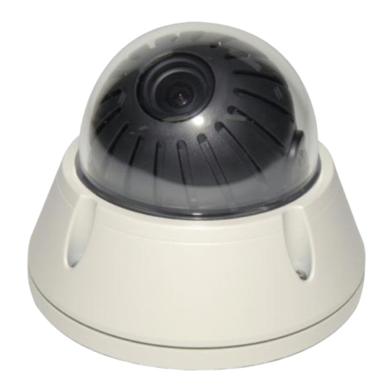
- Page 1 VVRD28V12DN-650 Installation manual Ultra Hi-resolution (650TVL), vandal resistant, day/night, vari-focal dome. Including scene analytics and alarm output functions...
-
Page 3: Important Safety Instructions
IMPORTANT SAFETY INSTRUCTIONS 1. Read these instructions. 2. Keep these instructions. 3. Heed all warnings. 4. Follow all instructions. 5. Do not use this apparatus near water. 6. Clean only with dry cloth. 7. Do not block any ventilation openings. Install in accordance with the m anufacturer‟s instructions. -
Page 4: Table Of Contents
CONTENTS OF PACKAGE The package contains the following Camera in Housing -----------------------------1no Instruction Manual (This Document)--------1no Accessory Kit for Installing -------------------1no Drilling guide label ------------------------------1no TABLE OF CONTENTS INTRODUCTION --------------------------------------------------------------------------------------- 4 CAMERA CONNECTIONS -------------------------------------------------------------------------- 6 INSTALLATION ----------------------------------------------------------------------------------------- 8 LENS ADJUSTMENT --------------------------------------------------------------------------------- 9 DC AUTO IRIS LENS --------------------------------------------------------------------------------- 9 OPERATING CAMERA ------------------------------------------------------------------------------- 9 CAMERA ADJUSTMENT ---------------------------------------------------------------------------- 9... -
Page 5: Introduction
INTRODUCTION The camera provides high-quality image using a Sony Wide Dynamic 1/3” Super-HADII PS 960H (Effio) CCD and digital signal processing LSIs. Features: 1/3” Super-HADII PS 960H CCD (Sony Effio) Super high-resolution of 650TV lines 0.4 lux(Colour), 0.04 lux(B/W), 0.001 lux(Low-Shutter) @ F1.4 Sensitivity Auto Electronic Shutter [1/50 ~ 1/100,000] and manual electronic shutter modes [1/50 ~ 1/10,000] On Screen Display (OSD) -
Page 6: Camera Connections
CAMERA CONNECTIONS Connection Cable Description COLOR Description AC24V/DC12V WHITE AC24V/DC12V ORANGE ADKEY BROWN BLUE RS485(-) GREEN RS485(+) YELLOW ALARM OUT GREY DN EXT-IN BLACK&WHITE DN EXT-OUT BLACK SKY BLUE Not used PINK Not used 1) External Day/Night Control: To select Day/Night mode using external equipment, connect control lines to the appropriate terminals. - Page 7 Power Input Terminal RED: WHITE If using a 12vDC PSU then it is recommended it is not less than 0.75A. 4) Camera Control GREEN: RS485+ BLUE: RS485- 5) AD Control via optional hand held set up controller (VZM22/REM) GND Terminal/Brown AD Key...
-
Page 8: Installation
INSTALLATION 1. Loosen the four torx screws located midway up the front of the housing leave the screws loose in the front portion. (Fig. 1) 2. Drill the mounting location, using the bottom of the housing as a Drilling guide label. (Fig. -
Page 9: Lens Adjustment
LENS ADJUSTMENT Field of view: Adjust setting from Telephoto (T) to wide (W) field of View. Focus: Adjust lens focus from near (N) to infinity. DC AUTO IRIS LENS 2.8~12mm 1/3" CCD Image Size Focal Length 2.8-12mm Aperture 1 : 1.4 Ratio Angular Horizontal... -
Page 10: Menu Tree
Local setup of the camera can be achieved by connecting a portable monitor to the set up video out put (No.6 in the image above). The OSD menu can be accessed by pressing button No. 1. Navigation of the menus is achieved by using the other buttons as detailed above. -
Page 11: Camera Adjustment
CAMERA ADJUSTMENT White Balance 1) Auto(Auto White Balance) : AWB mode (1800ºK ~10500ºK) 2) Push/Hold: Push & Hold Mode. To find the Optimal setting for the current environment, place a sheet of white paper in front of the camera, select Hold and press the Enter button. 3) CRS Mode (Colour Rolling Suppression): Function is not used on this camera. - Page 12 5) Spot (User Setting BLC area): Spot metering mode on. Posi: OSD mode to adjust the position of the spot metering area. Size: OSD mode to adjust the size of the spot metering area. 6) Zone (Preset BLC area): Fixed metering area mode. (1-9). Mask 1) Mask: Selects mask area to be set (1-15).
- Page 13 Motion Trace: When selected it will „box‟ the moving objects. Tracks an object through a scene and generates an alarm. Face Trace: Face Trace mode on. Tracks a face through a scene and generates an alarm. ...
- Page 14 If an object is passing too fast through the two detection areas, the counting may fail to operate. Then in this case, increase the space between the two zones or decrease the size of the zones. If the passing object is too long, counting results can be inaccurate. Then in this case, increase the space between the two zones or decrease the size of the zones.
- Page 15 Picture/DNR 1) Sharpness: Adjusts the sharpness of outlines (0~15) 2) Resolution: Selects resolution mode (Low/Mid/High) 3) 2D-NR: Select 2D noise reduction level (0~6) 2D-NR : Noise reduction on a frame 4) 3D-NR: Select 3D noise reduction level (0~31) 3D-NR : Noise reduction through the several frame 5) DNR Demo: Select DNR Demo Display On/Off using the Left and Right Buttons None DNR Effect...
- Page 16 5) Frame Control: Select term of refresh rate for output video. This function is useful to reduce the recording to data storage. Func: Select frame control mode to ON/OFF, and Auto. Auto mode: When motion is not detected, the video output is being refreshed in the programmed interval.
-
Page 17: System Setup
Cam ID: Select the camera ID (001 - 255). Baud Rate: Select serial communication speed (2400/4800/9600/19200). Protocol: RS-485 protocol. (COMMAND / VISTA / FASTRAX / PELCO-D / PELCO-P) ( Set to COMMAND when using hand held set up tool) Title: Edit camera title. - Page 18 Alarm : The alarm output (Yellow and Black pair) can be activated by the Detection or Scene change functions is configured as follows: Period: Alarm out period (5sec/10sec/20sec/30sec/1min/5min/Cont.) Snooze: Alarm out snooze(Off/5sec/10sec/20sec/30sec/1min/5min) (This is the period of time before the alarm will become armed again after an alarm has cleared) ...
- Page 19 5) White Pixel Det Exe: Press Enter button to start the White Pixel Compensation mode. ENT to Adj: Press Enter button to start White Pixel Compensation mode. Proc: Process is running finding the white pixels. ( Please wait) ...
-
Page 20: External Dimension
EXTERNAL DIMENSION 2.5mm, Window Size impact-resistant P.C (LEXAN) 10cm diameter Cable Entry One 23mm opening holes Weight – Unit: 700 g Shipping: 960 kg... -
Page 21: Specifications
1.0 Vp-p (75 ohm, composite) S/N ratio 50dB (AGC OFF) Camera control RS485 (Vista RS485, Fastrax, Pelco D, Pelco P) Lens 2.8mm~12.0mm/F1.4 D&N DC IRIS Vari-Focal Lens White Balance Auto / CRS / Push&Hold / Indoor / Outdoor / FL / User... - Page 23 Norbain SD Ltd 210 Wharfdale Road Winnersh Triangle Wokingham Berkshire RG41 5TP Subject to change without notice...
Need help?
Do you have a question about the VVRD28V12DN-650 and is the answer not in the manual?
Questions and answers