Table of Contents
Advertisement
Available languages
Available languages
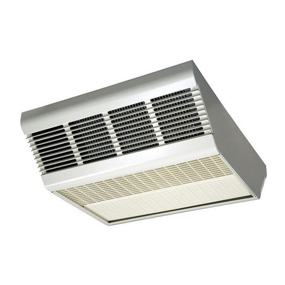
CDF500 Series
Ceiling Mounted
Fan Forced Heaters
Installation, Operation & Maintenance Instructions
Specifications
Model
Kw
1
CDF552SE
5/3.8/2.5
CDF547SE
4/3/2
CDF548SE
4/3/2
CDF557SE
5/3.8/2.5
CDF558SE
5/3.8/2.5
Model
Kw
1
CDF552RE
5/3.8/2.5
CDF547RE
4/3/2
CDF548RE
4/3/2
CDF557RE
5/3.8/2.5
CDF558RE
5/3.8/2.5
(1) Factory wired for highest wattage, field convertible to lower wattages.
(2) Factory wired 1Ø, field convertible to 3Ø.
(3) On dual phase units, maximum amp draw is listed.
(4) Temperature difference at highest rated wattage.
CAUTION - TO REDUCE RISK OF FIRE AND ELECTRIC
SHOCK OR INJURY TO PERSONS, OBSERVE THE
FOLLOWING:
1. To prevent electrical shock, disconnect all power coming to
heater at main service panel before wiring or servicing.
2. All wiring must be in accordance with the National and Local
Electrical Codes and the heater must be grounded as a pre-
caution against possible electric shock.
3. Verify the power supply voltage coming to heater matches
the ratings printed on the heater nameplate before energiz-
ing.
4. This heater is intended for ceiling installation ONLY. Do not
install the heater closer than 12" (305 mm) to any wall for
4000W models and 24" (609 mm) to any wall for 5000W
models.
5. Do not insert or allow foreign objects to enter any ventilation
or exhaust opening as this may cause an electric shock, fire,
or damage to the heater.
Surface Mounted
BTU/Hr. (000)
Volts
17.2/13.0/8.5
240
13.7/10.2/6.8
277
13.7/10.2/6.8
208
17.2/13.0/8.5
277
17.2/13.0/8.5
208
Recessed Mounted
BTU/Hr. (000)
Volts
17.2/13.0/8.5
240
13.7/10.2/6.8
277
13.7/10.2/6.8
208
17.2/13.0/8.5
277
17.2/13.0/8.5
208
WARNING
SAVE THESE INSTRUCTIONS
Description
Marley downflow ceiling mounted heaters are designed for
recessed or surface applications. Surface mounted heaters
extend only six inches into the room. Recessed mounted
heaters recess only seven inches into the ceiling. Mounts
easily into 2 X 2 foot ceiling grids.
Phase
Amps
2
3
1-3
20.8/15.8/10.4
1
14.5/10.8/7.2
1-3
19.2/14.4/9.6
1
18.1/13.7/9.0
1-3
24.0/18.2/12.0
Phase
Amps
2
3
1-3
20.8/15.8/10.4
1
14.5/10.8/7.2
1-3
19.2/14.4/9.6
1
18.1/13.7/9.0
1-3
24.0/18.2/12.0
!
6. To prevent a possible fire, do not block air intakes or
exhaust in any manner. Keep combustible materials, such
as crates, drapes, etc., away from heater.
7. A heater has hot and arcing (sparking) parts inside. Do not
use it in areas where gasoline, paint, or flammable liquids
are used or stored.
8. This heater is not approved for use in corrosive atmos-
pheres such as marine, green house, or chemical storage
areas.
9. The heater enclosure must be securely mounted to ceiling
or framing capable of supporting the heater (45 lbs/20.4 kg).
Failure to do so could allow heater to fall.
10. Do not operate heater without outlet grilles installed. When
installing grilles with louver guides, make sure guides drop
into position so they cannot slide out during use.
CFM (dm3/s)
°F
4
283 (133.5)
45
283 (133.5)
51
283 (133.5)
51
283 (133.5)
45
283 (133.5)
45
CFM (dm3/s)
°F
4
283 (133.5)
45
283 (133.5)
51
283 (133.5)
51
283 (133.5)
45
283 (133.5)
45
Advertisement
Table of Contents

Subscribe to Our Youtube Channel
Related Manuals for Marley CDF552SE


Summary of Contents for Marley CDF552SE
- Page 1 CDF500 Series Description Marley downflow ceiling mounted heaters are designed for recessed or surface applications. Surface mounted heaters Ceiling Mounted extend only six inches into the room. Recessed mounted heaters recess only seven inches into the ceiling. Mounts Fan Forced Heaters easily into 2 X 2 foot ceiling grids.
-
Page 2: Important Safety Information
IMPORTANT SAFETY INFORMATION 7. Position the surface mounting plate against the ceiling and secure with bolts or screws (Figure 2). See Warning No. 9, page 1. Connect the ground wire to the green ground screw on the surface mounting plate. FAILURE TO INSTALL THE FOUR MOUNTING NUTS TO 8. - Page 3 Surface Mounting Grounding Screw Optional Plate Disconnect Switch (CDFDS) Screws Power Supply or Bolts Stud (4) 7/8” & 1 / 8 ” (22.2 mm & Cable Cable or (Not Supplied) 28.5 mm) Nested Knockout Conduit Connector 12” (305 mm) Min. 4 kW 24”...
- Page 4 16. Connect the ground wire to the green ground screw on the recess mounting box. TO REDUCE THE RISK OF FIRE OR PERMANENT DAMAGE 17. After wiring is complete, replace and secure the side of the TO THE HEATER, THERMOSTAT MUST BE WIRED AS recess mount ing box previously removed in Step 3.
- Page 5 Grounding Power Supply 1/2” (12.2 mm) Knockout Screw Cable 7/8” & 1 / 8 ” (22.2 & 28.5 mm) Nested Knockout Recess Mounting Stud (4) Screw (2) Optional Nut (4) Disconnect Switch (CDFDS) 7/8” & 1 ” (22.2 & 28.5 mm) Thumb Nested Knockout 1/2”...
- Page 6 Adjustable Discharge Grilles Custom Air Flow Patterns (Figure 12) Discharge Grille (2) 1. The discharge air pattern is deter mined by the arrangement of the discharge grilles. 2. Care must be taken when selecting location of heater. Refer Louver Guides to “Installation of Discharge Air Grilles”, page 5.
-
Page 7: Operation
Wiring Diagrams Optional Field Installed Wall Fan Delay Black Thermostat SPST or Internal CDFT Black Thermostat Accessory White Black Standard Wiring Diagram White Element 1 (Factory Wired) High Contactor Limit Blue Black Black Blue Element 2 Black Power Block Black Optional Field Installed Wall Fan Delay Black... -
Page 8: Maintenance
MAINTENANCE IMPORTANT INFORMATION TO PREVENT ELECTRICAL SHOCK, DISCONNECT ALL POWER TO HEATER AT MAIN SERVICE PANEL BEFORE SERVICING. 1. Once each year the heater should be cleaned to remove dust and foreign material which has collected during the heating season. 2. - Page 9 F F i i g g u u r r e e 1 1 5 5 – – R R e e p p a a i i r r P P a a r r t t s s I I l l l l u u s s t t r r a a t t i i o o n n f f o o r r C C e e i i l l i i n n g g M M o o u u n n t t e e d d F F a a n n F F o o r r c c e e d d H H e e a a t t e e r r s s Repair Parts List for Ceiling Mounted Fan Forced Heaters Ref. Part Number for Models: Description CDF552SE CDF547SE CDF548SE CDF557SE CDF558SE Qty.
-
Page 10: Limited Warranty
Marley Engineered Products Service Center. Within the limitations of this warranty, inoperative units should be returned to the nearest Marley authorized service cen- ter or the Marley Engineered Products Service Center, and we will repair or replace, at our option, at no charge to you with return freight paid by Marley. It is agreed that such repair or replacement is the exclusive remedy available from Marley Engineered Products. - Page 11 609 mm x 609 mm (2 pies x 2 pies). Instrucciones de instalación, operación y mantenimiento Especificaciones Montaje en Superficie Modelo BTU/Hr. (000) Voltios Fase Amperios PCM (dm3/s) °F CDF552SE 5/3.8/2.5 17.2/13.0/8.5 20.8/15.8/10.4 283 (133.5) CDF547SE 4/3/2 13.7/10.2/6.8 14.5/10.8/7.2 283 (133.5) CDF548SE 4/3/2 13.7/10.2/6.8...
-
Page 12: Instalación
IMPORTANTE INFORMACION DE SEGURIDAD 6. Pase el cable de suministro eléctrico a través del conector y deje aproximadamente 203 mm (8 pulg.) de conductor dentro de la placa de montaje en superficie. (El cable de suministro eléctrico debe ser de tamaño No. 10 AWG como EL CALENTADOR SE PUEDE CAER SI NO SE INSTALAN LAS mínimo, con capacidad de 90°C como mínimo. - Page 13 Placa de montaje Interruptor de en superficie desconexión opcional (CDFDS) Tornillo de conexión a tierra Agujero ciego encajado Tornillos o de 22.2 mm y 28.5 mm Cable de suministro pernos (no Pasador (4) (7/8 pulg. y 1 / 8 pulg.) eléctrico Conector suministrados)
- Page 14 4. Destape uno de los agujeros ciegos e instale un conector de 12. Instale y apriete firmemente cuatro tornillos (suministrados) cable o conducto (Figura 3). para fijar la placa frontal empotrada en la sección del calen- tador (Figura 3). 5. Instale el interruptor de desconexión opcional CDFDS (si es necesario, según como se muestra en la Figura 3).
- Page 15 Agujero ciego de 12.2 mm (1/2 pulg.) Cable de Tornillo de conexión a suministro Agujero ciego encajado eléctrico tierra de 22.2 y 28.5 mm (7/8 pulg. y 1 / 8 pulg.) Caja de montaje Pasador (4) empotrado Tuerca (4) Tornillo (2) Interruptor de desconexión Agujero ciego encajado de...
- Page 16 Patrón personalizado Disposición de las rejillas Rejilla de descarga (2) de flujo del aire del aire de descarga PATRON DE AIRE ESTRECHO: para aplicaciones de cielos rasos altos (3352 mm [11 pies] a 4267 mm [14 pies]), concentra el aire calentado para garantizar una penetración total hasta el nivel Guías de rejilla del piso.
-
Page 17: Operación
Diagramas de Cableado Retardo del ventilador Termóstato unipolar opcional de la Negro instalación del campo o termóstato Negro interno 2YU46 auxiliar Blanco Negro Diagrama de cableado estándar Blanco Rojo Elemento 1 (Cableado en fábrica) Límite Contacto alto Azul Negro Negro Azul Rojo Elemento 2... -
Page 18: Mantenimiento
MANTENIMIENTO INFORMACIÓN IMPORTANTE PARA EVITAR EL RIESGO DE CHOQUE ELÉCTRICO, DESCONECTE TODA LA ALIMENTACIÓN ELÉCTRICA PARA EL CALENTADOR EN EL PANEL PRINCIPAL DE SERVICIO ANTES DE HACER CUALQUIER TRABAJO DE MANTENIMIENTO. 1. Se recomienda limpiar el calentador una vez por año para eliminar el polvo y todo material extraño que se haya acumulado durante la temporada de uso de la calefacción. - Page 19 Juego de Junta de Ajuste Auxiliar 2YU47 Lista de Partes de Reparación para los Calentadores de Tiro Forzado por Ventilador para Montaje en Cielo Raso No. de Número de Parte para Modelos: Ref. Descripción CDF552SE CDF547SE CDF548SE CDF557SE CDF558SE Cant. Elemento...
-
Page 20: Garantía Limitada
Marley más cercano, o al Centro de Servicio de Marley Engineered Products, y nosotros lo repararemos o reemplazaremos, a nuestra opción, sin cargo para usted, con el flete de retorno pagado por Marley. Se acuerda que tal reparación o reemplazo es el único recurso que Marley Engineered Products pone a su disposición. - Page 21 S'installe aisément dans des panneaux de 2 pi x 2 pi des plafonds suspendus. Instructions d'installation, d’utilisation et d'entretien Spécifications En applique Modèle BTU/h (000) Volts Phase Ampères PCM (dm3/s) °F CDF552SE 5/3,8/2,5 17,2/13,0/8,5 20,8/15,8/10,4 283 (133,5) CDF547SE 4/3/2 13,7/10,2/6,8 14,5/10,8/7,2 283 (133,5) CDF548SE 4/3/2...
- Page 22 INFORMATIONS IMPORTANTES SUR LA SÉCURITÉ 6. Acheminer le câble d'alimentation à travers le connecteur en laissant environ 203 mm (8 po) à l'intérieur de la plaque d'applique. (Le câble d'alimentation doit être de no 10 AWG au minimum avec caractéris-tique nominale minimale de 90 NÉGLIGER D'INSTALLER LES QUATRE ÉCROUS DE MON- °C.
- Page 23 Plaque de montage en applique Vis de mise à la terre Disjoncteur en Goujon (4) option (CDFDS) Alvéole défonçable 22,2 mm et 28,5 mm Panneau Câble d'alimentation (7/8 po et 1 Vis et boulons latéral électrique Fil ou connecteur (non fournis) de conduit Alvéole défonçable 305 mm (12 po) min.
- Page 24 7. Pour câbler le radiateur, thermostat réduire la puissance ou con- vertir d'une tension monophasée à une tension triphasée, con- sulter « Conversion sur le site à une puissance plus basse » ou L'ENVELOPPE DU RADIATEUR DOIT ÊTRE INSTALLÉE DE «...
- Page 25 7. Acheminer le câble d'alimentation à travers le connecteur en laissant environ 203 mm (8 po) à l'intérieur de la boîte d'en- Câble d'alimentation électrique castrement. (Le câble d'alimentation doit être de n 10 AWG Vis de mise à la terre au minimum avec caractéris-tique nominale minimale de 90 °C.) 8.
- Page 26 Installation des grilles d’evacuation d’air (voir les Figures 9, 10 et 11) A A g g e e n n c c e e m m e e n n t t d d e e l l a a g g r r i i l l l l e e C C o o n n f f i i g g u u r r a a t t i i o o n n p p e e r r s s o o n n n n a a l l i i s s é...
- Page 27 Schémas de câblage Temporisation de ventilateur Noir Noir Blanc Noir Schéma de Blanc câblage standard (Câblage Élément 1 Rouge de l'usine) Limite Contacteur supérieure Bleu Noir Noir Rouge Bleu Élément 2 Noir Ventilateur Bloc d'alimenta- tion Noir Noir Temporisation de ventilateur Noir Noir...
-
Page 28: Entretien
ENTRETIEN INFORMATION IMPORTANTE AFIN D'ÉVITER UN RISQUE DE DÉCHARGE ÉLECTRIQUE, COUPER TOUTE L'ALIMENTATION DU RADIATEUR AU NIVEAU DU PANNEAU DE SERVICE PRINCIPAL AVANT D'EFFECTUER L'ENTRETIEN. 1. Nettoyer le radiateur une fois par année pour enlever la poussière et les corps étrangers qui se sont accumulés pen- dant la saison de chauffage. - Page 29 F F i i g g u u r r e e 1 1 7 7 – – I I l l l l u u s s t t r r a a t t i i o o n n d d e e s s p p i i è è c c e e s s d d é é t t a a c c h h é é e e s s p p o o u u r r r r a a d d i i a a t t e e u u r r s s à à a a i i r r p p u u l l s s é é i i n n s s t t a a l l l l é é s s a a u u p p l l a a f f o o n n d d e e t t t t r r o o u u s s s s e e d d e e g g a a r r n n i i t t u u r r e e 2 2 Y Y U U 4 4 7 7 Liste des pièces détachées pour radiateurs à air pulsé installés au plafond et trousse de garniture 2YU47 Nº de Numéro de pièce pour modèles: réf. Description CDF552SE CDF552SE CDF548SE CDF557SE CDF558SE Qté...
-
Page 30: Garantie Limitée
être retourné au centre de réparation agréé par Marley le plus près ou au centre de réparation de la société Marley Engineered Products. Il sera ensuite gratuitement réparé ou remplacé, à notre discrétion, et les frais de port de retour seront pris en charge par Marley. Il est entendu que cette réparation ou ce remplace- ment constitue le seul et unique recours disponible auprès de la société...
Need help?
Do you have a question about the CDF552SE and is the answer not in the manual?
Questions and answers