Table of Contents
Advertisement
Available languages
Available languages
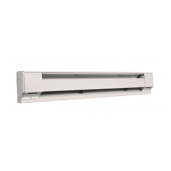
Electric Baseboard
Heaters
2500 & C2500 Series
Installation, Operation & Maintenance Instructions
GENERAL
This heater is designed to provide years of efficient, trouble free operation as a primary or supplementary heat source for comfort
heating in residential and commercial applications. Baseboard heaters must be thermostatically controlled for efficient, safe opera-
tion. A thermostat is not provided with this heater. However, a single or double pole thermostat accessory is available for installa-
tion into this heater at your place of purchase, or the heater may be connected to any suitable wall mounted thermostat that will
meet the electrical load requirements. Installation or use of this product in any manner not described herein will void the warranty
and could result in injury, damage to property, or permanent damage to heater.
WHEN USING ELECTRICAL APPLIANCES, BASIC PRECAU-
TIONS SHOULD ALWAYS BE FOLLOWED TO REDUCE
THE RISK OF FIRE, ELECTRIC SHOCK, AND INJURY TO
PERSONS, INCLUDING THE FOLLOWING:
1. Read all instructions before installing or using the heater.
2. A heater has hot and arcing or sparking parts inside, Do not
use in areas where gasoline or flammable liquids are used
or stored.
3. This heater is hot when in use. To avoid burns, do not let
bare skin touch hot surfaces. Keep combustible materials,
such as furniture, pillows, bedding, papers, clothes, and cur-
tains away from heater.
NAMEPLATE
2543NWC
MODEL NO.
BASEBOARD HEATER
PLINTHE CHAUFFANTE
VOLTS AC
60HZ
WATTS
240/208
750/546
AMPS
3.1/2.7
MARLEY ENGINEERED PRODUCTS
BENNETTSVILLE, SC 29512
Figure 1: Nameplate Location
IMPORTANT INSTRUCTIONS
WARNING
DATE CODE
1009
54E1 LISTED
BASEBOARD HEATER
PATENT PENDING
4104-2109-265
SAVE THESE INSTRUCTIONS
!
4. To prevent a possible fire, do not block air intakes or
exhaust in any manner.
5. Do not insert or allow foreign objects to enter any ventilation
or exhaust opening as this may cause an electric shock or
fire, or damage the heater.
6. Serious injury or death could result from electric shock.
Make sure electrical power supply circuit coming to heater
is disconnected at main disconnect or service panel before
installing or servicing this heater.
Table 1
Total Amps
AWG. Wire Size
0 thru 12
12.1 thru 16
16.1 thru 24
Table 2: Net Volumes of Wiring Compartment
DESCRIPTION
Heater Only (Each Wiring Compartment)
Heater W/SP Thermostat
Heater W/DP Thermostat
Heater W/Heat-Cool Switch Receptacle
Heater W/Duplex Receptacle
Heater W/DP Disconnect Switch
Heater W/Power Relay
Heater W/Transformer Relay
Minimum
Circuit Breaker
or Fuse Size
(Copper)
#14
15 amp
#12
20 amp
#10
30 amp
CUBIC
CUBIC
INCHES CM
14.96
241
11.18
180
11.18
180
9.51
153
11.18
180
11.18
180
10.76
174
2.93
47
Advertisement
Table of Contents

Subscribe to Our Youtube Channel
Related Manuals for Marley 2500 & C2500 Series


Summary of Contents for Marley 2500 & C2500 Series
-
Page 1: Important Instructions
AMPS 54E1 LISTED 3.1/2.7 Heater W/DP Thermostat 11.18 BASEBOARD HEATER Heater W/Heat-Cool Switch Receptacle 9.51 PATENT PENDING MARLEY ENGINEERED PRODUCTS Heater W/Duplex Receptacle 11.18 4104-2109-265 BENNETTSVILLE, SC 29512 Heater W/DP Disconnect Switch 11.18 Heater W/Power Relay 10.76 Figure 1: Nameplate Location Heater W/Transformer Relay 2.93... -
Page 2: Installation Instructions
4. Wireway Cover - Commercial Baseboard Only 11. Do not remove or bypass the safety limit control as this a. The wireway cover is a factory installed feature of Marley could allow heater to become a fire hazard – see Figure 4. -
Page 3: Maintenance Instructions
5. Loosen screw in built-in cable clamp (Figure 4) or remove desired knockout from heater wiring compartment. Install Mounting perforations power cable into wiring compartment allowing at least 6 in (153mm) of cable for connection to heater. To install two power cables using the built-in cable clamp, bend tab cover- ing second hole up and back to rear wall of wiring compart- ment. -
Page 4: Limited Warranty
Marley Engineered Products Service Center. Within the limitations of this warranty, inoperative units should be returned to the nearest Marley authorized service cen- ter or the Marley Engineered Products Service Center, and we will repair or replace, at our option, at no charge to you with return freight paid by Marley. It is agreed that such repair or replacement is the exclusive remedy available from Marley Engineered Products. -
Page 5: Instrucciones Importantes
Calefactor con enchufe hembra para BASEBOARD HEATER Interruptor Calor-Frío 9.51 Calefactor con enchufe hembra doble 11.18 PATENT PENDING MARLEY ENGINEERED PRODUCTS Calefactor con interruptor de desconexión bipolar (DP) 11.18 4104-2109-265 BENNETTSVILLE, SC 29512 Calefactor con relé de potencia 10.76 Calefactor con relé con transformador 2.93... -
Page 6: Instrucciones De Instalación
Espacios libres mínimos a. La cubierta del canal de cables es un elemento de los calefac- tores de zócalo comerciales de Marley instalado en fábrica Del calefactor al piso: el calefactor puede montarse directamente sobre el piso terminado o, si se desea, por encima del piso (por ejemplo, Pueden encaminarse por el canal de cables dos cables o cuatro sobre el zócalo). -
Page 7: Instrucciones De Operación
cables desde la parte posterior del calefactor. Retire los prepun- zonados de las zonas del canal en ambas cajas de terminales. Perforaciones de montaje c. Inserte los manguitos aisladores plásticos del juego de piezas (en el compartimiento de cables) en los agujeros de los prepunzona- dos. -
Page 8: Garantía Limitada
Marley más cercano, o al Centro de Servicio de Marley Engineered Products, y nosotros lo repararemos o reemplazaremos, a nuestra opción, sin cargo para usted, con el flete de retorno pagado por Marley. Se acuerda que tal reparación o reemplazo es el único recurso que Marley Engineered Products pone a su disposición. -
Page 9: Instructions Importantes
BASEBOARD HEATER Radiateur avec prise duplex 11,18 Radiateur avec interrupteur de coupure 11,18 PATENT PENDING MARLEY ENGINEERED PRODUCTS 4104-2109-265 Radiateur avec relais d’alimentation 10,76 BENNETTSVILLE, SC 29512 Radiateur avec relais de transformateur 2,93 Figure 1 : Emplacement de la plaque signalétique... -
Page 10: Instructions D'installation
3. Si d’autres accessoires de Marley sont à utiliser avec ce radiateur, référez-vous aux instructions d’installation fournies pour installer et 11. N’enlevez pas et ne contournez pas le contrôle de limite de sécu- rité... -
Page 11: Instructions D'utilisation
du radiateur. Enfoncez les trous dans les zones de canal aux deux boîtiers de terminaison. Perforations pour montage c. Insérez les isolants en plastique du kit de pièces (dans le compartiment de câblage) dans les trous enfoncés. d. Câblez le radiateur en fonction des schémas de câblage de la Figure 5. -
Page 12: Garantie Limitée
être retourné au centre de réparation agréé par Marley le plus près ou au centre de réparation de la société Marley Engineered Products. Il sera ensuite gratuitement réparé ou remplacé, à notre discrétion, et les frais de port de retour seront pris en charge par Marley. Il est entendu que cette réparation ou ce remplace- ment constitue le seul et unique recours disponible auprès de la société...
Need help?
Do you have a question about the 2500 & C2500 Series and is the answer not in the manual?
Questions and answers