Table of Contents
Advertisement
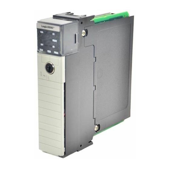
ControlLogix Controller and Memory Board
Catalog Numbers 1756-L1, 1756-L1M1, 1756-L1M2,
1756-L1M3, 1756-L55, 1756-L55M12, 1756-L55M13,
1756-L55M14, 1756-L55M16, 1756-L55M22,
1756-L55M23, 1756-L55M24, 1756-L61, 1756-L62,
1756-L63, 1756-L64, 1756-L65, 1756-M1, 1756-M2,
1756-M3, 1756-M12, 1756-M13, 1756-M14,
1756-M16, 1756-M22, 1756-M23, 1756-M24,
1784-CF64, 1784-CF128
Topic
Installation Instructions
Page
3
4
4
4
5
6
7
8
9
11
Advertisement
Table of Contents

Related Manuals for Rockwell Automation 1756-L1


Summary of Contents for Rockwell Automation 1756-L1
-
Page 1: Table Of Contents
Installation Instructions ControlLogix Controller and Memory Board Catalog Numbers 1756-L1, 1756-L1M1, 1756-L1M2, 1756-L1M3, 1756-L55, 1756-L55M12, 1756-L55M13, 1756-L55M14, 1756-L55M16, 1756-L55M22, 1756-L55M23, 1756-L55M24, 1756-L61, 1756-L62, 1756-L63, 1756-L64, 1756-L65, 1756-M1, 1756-M2, 1756-M3, 1756-M12, 1756-M13, 1756-M14, 1756-M16, 1756-M22, 1756-M23, 1756-M24, 1784-CF64, 1784-CF128 Topic Page... - Page 2 2 ControlLogix Controller and Memory Board Topic Page Required System Components Firmware Revisions Preparing the Chassis Remove the Controller from the Chassis Installing a Memory Board on a ControlLogix5550 or ControlLogix5555 Controller Installing a CompactFlash Card in a Controller Connecting a Battery Installing the Controller into the Chassis Check the BAT Status Indicator Checking the OK Status Indicator...
-
Page 3: Important User Information
In no event will Rockwell Automation, Inc. be responsible or liable for indirect or consequential damages resulting from the use or application of this equipment. -
Page 4: Explosion Hazards
4 ControlLogix Controller and Memory Board Explosion Hazards An electrical arc can occur if you: WARNING insert or remove the CompactFlash card. insert or remove the controller while backplane power is on. connect or disconnect the battery. connect or disconnect the serial cable with power applied to this module or the serial device on the other end of the cable. -
Page 5: Environment And Enclosure
ControlLogix Controller and Memory Board 5 Environment and Enclosure This equipment is intended for use in a Pollution Degree 2 industrial ATTENTION environment, in overvoltage Category II applications (as defined in IEC publication 60664-1), at altitudes up to 2000 m (6561 ft) without derating. -
Page 6: North American Hazardous Location Approval
6 ControlLogix Controller and Memory Board North American Hazardous Location Approval The following information applies when Informations sur l’utilisation de cet operating this equipment in hazardous équipement en environnements dangereux. locations. Products marked "CL I, DIV 2, GP A, B, C, D" are suitable for Les produits marqués "CL I, DIV 2, GP A, B, C, D"... -
Page 7: European Hazardous Location Approval
ControlLogix Controller and Memory Board 7 European Hazardous Location Approval European Zone 2 Certification (The following applies when the product bears the Ex or EEx Marking) This equipment is intended for use in potentially explosive atmospheres as defined by European Union Directive 94/9/EC. The LCIE (Laboratoire Central des Industries Electriques) certifies that this equipment has been found to comply with the Essential Health and Safety Requirements relating to the design and construction of Category 3 equipment intended for use in potentially explosive... -
Page 8: Before You Begin
Read this section for important information about using these products, noting that this publication covers the products shown in the table. Product Cat. No. Series ControlLogix5550 controller 1756-L1, 1756-L1M1, 1756-L1M2, 1756-L1M3 ControlLogix5555 controller 1756-L55, 1756-L55M12, 1756-L55M13, 1756-L55M14, 1756-L55M16, 1756-L55M22, 1756-L55M23, 1756-L55M24 ControlLogix5561 controller... -
Page 9: Replace A Suspected Failed Controller
ControlLogix Controller and Memory Board 9 Replace a Suspected Failed Controller To replace a failed controller, do the following. 1. Cycle power to the chassis. 2. Make sure the OK status indicator is solid red, noting that if the OK status indicator is not solid red, the controller does not require replacement. - Page 10 10 ControlLogix Controller and Memory Board 4. Insert the battery. Series B Series A COMPACT FLASH 1-DCD DSR-6 2-RXD RTS-7 3-TXD CTS-8 4-DTR N/C-9 5-GND RS232 Insert 1 To Eject 1 + 2 BATTERY DATE BATTERY 42523 PORT 5. Insert the key, and turn it to the PROG position. 6.
-
Page 11: Resolving Common Errors
ControlLogix Controller and Memory Board 11 Resolving Common Errors Before you change a memory board, update the controller to a revision that IMPORTANT is compatible with the memory board that you intend to install. Make sure you use the correct firmware revision. To resolve common errors, see the following table. -
Page 12: Required System Components
12 ControlLogix Controller and Memory Board Required System Components These components ship with the controller. Component Description Series A controllers: 1756-BA1 battery Series B controllers: 1756-BA2 battery You can use these components with the controller. To maintain memory longer than is available with the battery, this option IMPORTANT maintains memory only while the controller is in the chassis. - Page 13 ControlLogix Controller and Memory Board 13 Optional Components Description Controller Component Add nonvolatile memory ControlLogix5550 Not available for this controller. ControlLogix5555 Memory board. ControlLogix5561 1784-CF64 Industrial ControlLogix5562 CompactFlash Card. ControlLogix5563 ControlLogix5564 ControlLogix5565 31376-M Maintain memory longer ControlLogix5550 Not available for this than is available with the controller.
-
Page 14: Firmware Revisions
14 ControlLogix Controller and Memory Board Memory Board Controller Memory Board ControlLogix5550 1756-M1, 1756-M2, 1756-M3 ControlLogix5555 No nonvolatile memory 1756-M12, 1756-M13, 1756-M14, 1756-M16 Nonvolatile memory 1756-M22, 1756-M23, 1756-M24 ControlLogix5561 Do not install a memory board. ControlLogix5562 ControlLogix5563 ControlLogix5564 ControlLogix5565 Firmware Revisions To update the firmware of a controller, install a firmware upgrade kit. - Page 15 Use the following table to determine which firmware revisions to use with your controller and memory board combination. Controller and Memory Board Combinations Controller and Series Use this revision or later Memory Board 1756-L1 None Any. 1756-L1M1 1756-L1M2 1756-L1M3 1756-L55M12 10.x or later.
-
Page 16: Preparing The Chassis
16 ControlLogix Controller and Memory Board Preparing the Chassis Before you install a controller: install a ControlLogix chassis. install a ControlLogix power supply. Remove the Controller from the Chassis You can install or remove a controller while chassis power is on and the system is operating. -
Page 17: Installing A Memory Board On A Controllogix5550 Or Controllogix5555 Controller
ControlLogix Controller and Memory Board 17 Installing a Memory Board on a ControlLogix5550 or ControlLogix5555 Controller Before you install or replace the memory board, disconnect the battery from ATTENTION the controller. Otherwise, you may damage the memory board. When you connect or disconnect the battery an electrical arc can occur. This WARNING could cause an explosion in hazardous location installations. - Page 18 18 ControlLogix Controller and Memory Board Remove the Side Plate of the Controller 1. Lay the controller on its side with the label facing up. 2. Remove the two screws that attach the side plate to the controller while wearing a grounding wriststrap. 3.
- Page 19 ControlLogix Controller and Memory Board 19 Remove the Existing Memory Board If the controller does not already have a memory board, as shown in the figure, refer to the Install the Memory Board section. 42527 1. Pull the plastic back edge of the controller out slightly to clear the tabs on the memory board.
- Page 20 20 ControlLogix Controller and Memory Board Install the Memory Board 1. Place the memory board over the connector and slide the memory board into the controller. Item Description Memory board Slot 40018 2. Pull the plastic back edge of the controller out slightly to clear the tabs of the memory board.
- Page 21 ControlLogix Controller and Memory Board 21 Replace the Side Plate 40019 1. Line up the hinge tabs on the side plate with the slots in the plastic housing of the controller. 2. Gently press the side plate against the controller. 3.
-
Page 22: Installing A Compactflash Card In A Controller
22 ControlLogix Controller and Memory Board Installing a CompactFlash Card in a Controller A 1784-CF64 or 1784-CF128 Industrial CompactFlash Card provides nonvolatile memory for a ControlLogix5561, ControlLogix5562, ControlLogix5563, ControlLogix5564, or a ControlLogix5565 controller. Install a CompactFlash Card in a Series A Controller 1. - Page 23 ControlLogix Controller and Memory Board 23 Install a CompactFlash Card in a Series B Controller When you insert or remove the CompactFlash card an electrical arc can occur. WARNING This could cause an explosion in hazardous location installations. Be sure that power is removed or the area is nonhazardous before proceeding.
- Page 24 24 ControlLogix Controller and Memory Board Remove a CompactFlash Card from a Series B Controller When you insert or remove the CompactFlash card an electrical arc WARNING can occur. This could cause an explosion in hazardous location installations. Be sure that power is removed or the area is nonhazardous before proceeding.
-
Page 25: Connecting A Battery
ControlLogix Controller and Memory Board 25 Connecting a Battery When you connect or disconnect the battery an electrical arc can occur. This WARNING could cause an explosion in hazardous location installations. Be sure that power is removed or the area is nonhazardous before proceeding. For Safety information on the handling of lithium batteries, including handling and disposal of leaking batteries, see Guidelines for Handling Lithium Batteries, publication AG-5-4-NOV04. - Page 26 26 ControlLogix Controller and Memory Board Install a Battery in a Series A Controller For a series A controller, connect only a 1756-BA1 battery or a 1756-BATM ATTENTION battery module. Other batteries may damage the controller. 1. Insert and connect the battery as shown. 2.
- Page 27 ControlLogix Controller and Memory Board 27 Install a Battery in a Series B Controller For a series B controller, connect only a 1756-BA2 battery. Other batteries may ATTENTION damage the controller. 1. Insert the battery with the arrow pointing up as shown. 2.
-
Page 28: Installing The Controller Into The Chassis
28 ControlLogix Controller and Memory Board Installing the Controller into the Chassis When you install a ControlLogix controller, you can: place the controller in any slot. use multiple controllers in the same chassis. You can install or remove a ControlLogix controller while chassis power is on and the system is operating. -
Page 29: Check The Bat Status Indicator
3. Check that the battery or battery module is correctly connected to the controller. 4. If the BAT status indicator remains on, install another battery. 5. If the BAT status indicator remains on after you complete the previous step, contact your Rockwell Automation representative or local distributor. Publication 1756-IN101L-EN-P - June 2008... -
Page 30: Checking The Ok Status Indicator
30 ControlLogix Controller and Memory Board Checking the OK Status Indicator 42525 1. Check the color of the OK status indicator. Then Actions Solid green The controller is OK and its No further actions are required. firmware has been updated. However, the revision of firmware must be compatible with your version of RSLogix 5000 software. - Page 31 ControlLogix Controller and Memory Board 31 3. Determine if the memory board has been replaced with a memory board with a different catalog number. For example, did you replace a 1756-M13 memory board with a 1756-M23 memory board? Then The controller is not operational. Contact your Rockwell Automation representative or local distributor.
-
Page 32: Update The Controller
32 ControlLogix Controller and Memory Board Update the Controller RSLogix 5000 software, version 10.0 or later, lets you update the firmware IMPORTANT of a controller as part of the download sequence. To update the controller, download your project and follow the prompts of the software. 1. - Page 33 ControlLogix Controller and Memory Board 33 6. Select the controller, and click OK. 42900 7. Select the revision level to which you want to update the controller and click Next. If the Revision list is empty, download a new upgrade kit. Some older IMPORTANT upgrade kits do not work with new controllers.
-
Page 34: Connecting A Serial Cable
34 ControlLogix Controller and Memory Board Connecting a Serial Cable If you connect or disconnect the serial cable with power applied to this module WARNING or the serial device on the other end of the cable, an electrical arc can occur. This could cause an explosion in hazardous location installations. - Page 35 ControlLogix Controller and Memory Board 35 To connect a workstation to the serial port, use one of these cables: 1756-CP3 serial cable 1747-CP3 cable from the SLC product family. If you use this cable, the controller door may not close. Item Description Workstation end...
-
Page 36: Interpreting The Status Indicators
36 ControlLogix Controller and Memory Board Interpreting the Status Indicators The following table describes the status indicators. Indicator Status Description The controller is in Program or Test mode. See Choosing the Operating Mode of the Controllers. Solid The controller is in Run mode. See Choosing the Operating Mode green of the... - Page 37 ControlLogix Controller and Memory Board 37 Indicator Status Description RS232 There is no activity. Solid Data is being received or transmitted. green For a Series A controller, the controller does not show this indication. Solid For a Series B controller, during power-down, the controller is green saving the project to its internal nonvolatile memory.
-
Page 38: Clear A Major Fault
Follow these steps if the problem persists: A. Before you cycle power to the controller, record the state of the OK and RS232 status indicators. B. Contact Rockwell Automation support. A. To get diagnostic information about the fault, see Knowledgebase document A92558072. To get the document, see the back of this publication. -
Page 39: Clear A Nonrecoverable Fault
B. Download the project to the controller. C. Return the controller to the Run/Remote Run mode. Solid red Contact your Rockwell Automation representative or local distributor. Follow these steps if the problem persists. 1. Before you cycle power to the controller, record the state of the OK and RS232 status indicators. -
Page 40: Choosing The Operating Mode Of The Controllers
40 ControlLogix Controller and Memory Board Choosing the Operating Mode of the Controllers Do you want to prevent Do you need to schedule a RSLogix 5000 software from ControlNet network? changing the mode? Turn the keyswitch to Do you want to execute the PROG (Program Turn the keyswitch to logic in the controller? -
Page 41: Specifications
ControlLogix Controller and Memory Board 41 Specifications Specifications - ControlLogix Controllers Cat. No. Memory Non- Backplane Power Ther- Weight, volatile Current Dissi- approx. Memory pation Dissi- Data and pation 5.1V Logic 1756-L55M22 750 KB 1.23 0.014 5.6 W 19.1 0.35 kg BTU/hr (12.5 oz) 1756-L55M23... -
Page 42: Publication 1756-In101L-En-P - June
42 ControlLogix Controller and Memory Board ControlLogix Controller Common Specifications - 1756-L1, 1756-L1M1, 1756-L1M2, 1756-L1M3, 1756-L55, 1756-L55M12, 1756-L55M13, 1756-L55M14, 1756-L55M16, 1756-L55M22, 1756-L55M23, 1756-L55M24, 1756-L61, 1756-L62, 1756-L63, 1756-L64, and 1756-L65 Attribute Value Temperature, operating IEC 60068-2-1 (Test Ad, Operating Cold), IEC 60068-2-2 (Test Bd, Operating Dry Heat), IEC 60068-2-14 (Test Nb, Operating Thermal Shock): 0 …... - Page 43 ControlLogix Controller and Memory Board 43 ControlLogix Controller Common Specifications - 1756-L1, 1756-L1M1, 1756-L1M2, 1756-L1M3, 1756-L55, 1756-L55M12, 1756-L55M13, 1756-L55M14, 1756-L55M16, 1756-L55M22, 1756-L55M23, 1756-L55M24, 1756-L61, 1756-L62, 1756-L63, 1756-L64, and 1756-L65 Attribute Value Conducted RF immunity IEC 61000-4-6: 10V rms with 1 kHz sine-wave 80% AM from 150 kHz…80...
- Page 44 44 ControlLogix Controller and Memory Board ControlLogix Memory Board Specifications - 1756-M1, 1756-M2, 1756-M3, 1756-M12, 1756-M13, 1756-M14, 1756-M16, 1756-M22, 1756-M23, and 1756-M24 Attribute Value Temperature, operating EC 60068-2-1 (Test Ad, Operating Cold), IEC 60068-2-2 (Test Bd, Operating Dry Heat), IEC 60068-2-14 (Test Nb, Operating Thermal Shock): 0 …...
- Page 45 ControlLogix Controller and Memory Board 45 Industrial CompactFlash Card Specifications - Industrial CompactFlash Card - 1784-CF64, 1784-CF128 Attribute Value User available memory 64 MB, 128 MB Nonvolatile memory Weight, approx. 14.2 g (0.5 oz) Temperature, operating IEC 60068-2-1 (Test Ad, Operating Cold), IEC 60068-2-2 (Test Bd, Operating Dry Heat), IEC 60068-2-14 (Test Nb, Operating Thermal Shock): 0…60 °C (32…140 °F)
- Page 46 46 ControlLogix Controller and Memory Board Certifications - ControlLogix Controller Certifications Cat. No. Certification Description 1756-L1, 1756-L55 UL Listed Industrial Control Equipment. See UL File E65584. CSA Certified Process Control Equipment. See CSA File LR54689C. CSA Certified Process Control Equipment for Class I, Division 2 Group A,B,C,D Hazardous Locations.
- Page 47 ControlLogix Controller and Memory Board 47 Certifications - ControlLogix Controller Certifications Cat. No. Certification Description 1756-L61, UL Listed Industrial Control Equipment, certified for US and c-UL-us Canada. See UL File E65584. 1756-L62, 1756-L63, UL Listed for Class I, Division 2 Group A,B,C,D Hazardous c-UL-us 1756-L64, Locations, certified for U.S.
- Page 48 48 ControlLogix Controller and Memory Board Certifications - ControlLogix Memory Board Cat. No. Certification Description 1756-M1, UL Recognized Component Industrial Control Equipment. See UL File E65584. 1756-M2 1756-M3 CSA Certified Process Control Equipment. See CSA File LR54689C. 1756-M12 CSA Certified Process Control Equipment for Class I, Division 2 1756-M13 Group A,B,C,D Hazardous Locations.
- Page 49 Product Certifications website, Provides declarations of conformity, http://ab.com certificates, and other certification details. You can view or download publications at http://literature.rockwellautomation.com. To order paper copies of technical documentation, contact your local Rockwell Automation distributor or sales representative. Publication 1756-IN101L-EN-P - June 2008...
- Page 50 50 ControlLogix Controller and Memory Board Notes: Publication 1756-IN101L-EN-P - June 2008...
- Page 51 ControlLogix Controller and Memory Board 51 Notes: Publication 1756-IN101L-EN-P - June 2008...
- Page 52 New Product Satisfaction Return Rockwell Automation tests all of its products to ensure that they are fully operational when shipped from the manufacturing facility. However, if your product is not functioning and needs to be returned, follow these procedures.
Need help?
Do you have a question about the 1756-L1 and is the answer not in the manual?
Questions and answers