Emerson Daniel 3812 Installation Manual
Liquid ultrasonic flow meter, for direct and remote mount meter electronics
Hide thumbs
Also See for Daniel 3812:
- Installation manual (142 pages) ,
- Maintenance and troubleshooting manual (104 pages)

Related Manuals for Emerson Daniel 3812


Summary of Contents for Emerson Daniel 3812
- Page 1 Installation manual 3-9000-765, Rev KA January 2019 ™ Daniel 3812 Liquid Ultrasonic Flow Meter for Direct and Remote Mount Meter Electronics...
- Page 3 Email • Customer Service: DanielCST.Support@Emerson.com • Customer Support: Daniel.TechnicalSupport@Emerson.com • Field Lifecycle Services: Tech.Service@Emerson.com • Asia-Pacific: danielap.support@emerson.com • Europe: danielEMA.cst@emerson.com Return Material Authorization (RMA) A Return Material Authorization (RMA) number must be obtained prior to returning any equipment for any reason. Access and fill in the RMA form for Daniel products clicking on the link below.
- Page 4 Signal words and symbols Pay special attention to the following signal words, safety alert symbols and statements: Safety alert symbol This is a safety alert symbol. It is used to alert you to potential physical injury hazards. Obey all safety messages that follow this symbol to avoid possible injury or death.
- Page 5 • Verify that this is the correct instruction manual for your Daniel product. If this is not the correct documentation, contact Daniel at 1-713-827-6314. You may also download the correct manual from: https://www.emerson.com/en-us/automation/ daniel. • Save this instruction manual for future reference.
- Page 6 • Verify that this is the correct instruction manual for your Daniel product. If this is not the correct documentation, contact Daniel at 1-713-827-6314. You may also download the correct manual from: https://www.emerson.com/en-us/automation/ daniel. • Read and understand all instructions and operating procedures for this product.
- Page 7 Notice THE CONTENTS OF THIS PUBLICATION ARE PRESENTED FOR INFORMATIONAL PURPOSES ONLY, AND WHILE EVERY EFFORT HAS BEEN MADE TO ENSURE THEIR ACCURACY, THEY ARE NOT TO BE CONSTRUED AS WARRANTIES OR GUARANTEES, EXPRESSED OR IMPLIED, REGARDING THE PRODUCTS OR SERVICES DESCRIBED HEREIN OR THEIR USE OR APPLICABILITY. ALL SALES ARE GOVERNED BY DANIEL'S TERMS AND CONDITIONS, WHICH ARE AVAILABLE UPON REQUEST.
- Page 8 Warranty and Limitations 1. LIMITED WARRANTY: Subject to the limitations contained in Section 2 herein, Daniel Measurement & Control, Inc. (“Daniel”) warrants that the licensed firmware embodied in the Goods will execute the programming instructions provided by Daniel, and that the Goods manufactured by Daniel will be free from defects in materials or workmanship under normal use and care and Services will be performed by trained personnel using proper equipment and instrumentation for the particular Service provided.
-
Page 9: Table Of Contents
3-9000-765 January 2019 Contents Chapter 1 Introduction.........................11 1.1 General overview of Daniel 3812 Liquid Ultrasonic Flow Meter............11 1.2 Typical applications........................11 1.3 Features and benefits of this product....................12 1.4 Acronyms, abbreviations and definitions..................12 1.5 Daniel MeterLink software......................15 1.6 Daniel 3812 Liquid Ultrasonic Flow meter design................16... - Page 10 Contents Installation manual January 2019 3-9000-765 3812 Liquid Ultrasonic Flow Meter...
-
Page 11: Chapter 1 Introduction
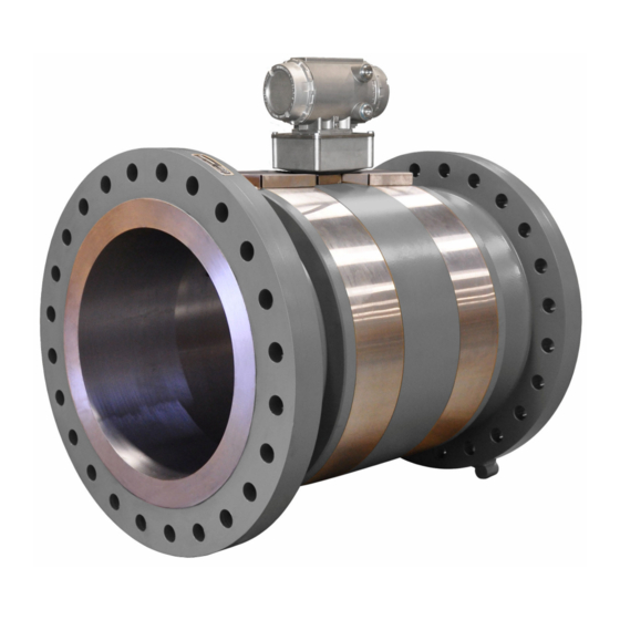
General overview of Daniel 3812 Liquid Ultrasonic Flow Meter Daniel 3812 Liquid Ultrasonic Flow Meters have direct mount or remote mount electronic options and various configurations that meet a broad range of customer requirements. Each meter comes fully assembled from Daniel Measurement and Control, Inc. and all parts and assemblies are tested prior to shipment. -
Page 12: Features And Benefits Of This Product
Introduction Installation manual January 2019 3-9000-765 Features and benefits of this product • Explosion-proof transmitter electronics enclosure with CPU Module, Power Supply, Intrinsic Safety Barrier Module • Intrinsically safe transducer electronics enclosure with the Acquisition Module • Daniel MeterLink (software for Daniel Ultrasonic Flow Meters) ®... - Page 13 Installation manual Introduction 3-9000-765 January 2019 Table 1-1: Acronyms, abbreviations and definitions (continued) Acronym or abbreviation Definition ASCII MODBUS A Modbus protocol message framing format in which ASCII characters are used to delineate the beginning and end of the frame. ASCII stands for American Standard Code for Information Interchange.
- Page 14 Introduction Installation manual January 2019 3-9000-765 Table 1-1: Acronyms, abbreviations and definitions (continued) Acronym or abbreviation Definition Kilohertz (103 cycles per second, frequency unit) Local Area Network Light-emitting Diode meter (length unit) cubic meters per day (volumetric flow rate) cubic meters per hour (volumetric flow rate) cubic meters per second (volumetric flow rate) milliamp (current unit) MAC Address...
-
Page 15: Daniel Meterlink Software
Daniel MeterLink may be downloaded at no charge from: https:// www.emerson.com/en-us/catalog/automation-solutions/measurement-instrumentation/ flow/daniel-meterlink Figure 1-1: Daniel MeterLink download and registration Select the MeterLink software and firmware bundle appropriate for your meter. Complete the Online registration form and you will receive a confirmation email with a hyperlink directing you to the download site. -
Page 16: Daniel 3812 Liquid Ultrasonic Flow Meter Design
Daniel 3812 Liquid Ultrasonic Flow meter design The Daniel 3812 Liquid Ultrasonic Flow Meter designs include a direct or remote mount electronics option and depending on the meter’s outside diameter, have a shroud cover protecting the transducers and cable assemblies. See... - Page 17 Installation manual Introduction 3-9000-765 January 2019 Figure 1-3: Direct mount electronics with latched single band shrouds and remote display A. Explosion-proof transmitter enclosure (CPU Module, Power Supply, I.S. Barrier Board, Backplane board, and optional LCD Board with glass endcap) B. Intrinsically-safe base enclosure includes Acquisition Module C.
- Page 18 Introduction Installation manual January 2019 3-9000-765 Figure 1-5: Direct mount electronics assembly with clamped band shrouds A. Explosion-proof transmitter enclosure (CPU Module, Power Supply, I.S. Barrier Board,Backplane board, optional LCD Board with glass endcap) B. Intrinsically-safe base enclosure includes Acquisition Module C.
- Page 19 E. Meter - body and split shrouds for transducer and cable assemblies Figure 1-8: Optional local display and glass endcap The Daniel 3812 Liquid Ultrasonic Flow Meter is a two-path (four transducers) in-line meter designed to measure the difference in signal transit time with and against the flow across one or more measurement path(s).
-
Page 20: Meter Specifications
The Daniel 3812 Liquid Ultrasonic Flow Meter’s U.L. safety listing is accomplished through the combination of an explosion-proof Transmitter Electronics Enclosure that houses the CPU Module, Power Supply board, I.S. Barrier board, Backplane board and optional LCD Display board. - Page 21 Installation manual Introduction 3-9000-765 January 2019 Table 1-2: Meter specifications (continued) Liquid Ultrasonic Flow Meter specifications Velocity range • 40.0 ft/s (12.2 m/s) (nominal) to 2.0 ft/s (0.6 m/s) • 48 fps (14.3 m/s) (over-range) Body and Flange Pressure rating range U.S.
- Page 22 Introduction Installation manual January 2019 3-9000-765 Table 1-2: Meter specifications (continued) Liquid Ultrasonic Flow Meter specifications Power Meter • 10.4 VDC to 36 VDC measured at the meter terminals • 11 W maximum power consumption Serial cable • Belden #9940 or equivalent (22 gauge) —...
- Page 23 Installation manual Introduction 3-9000-765 January 2019 Table 1-2: Meter specifications (continued) Liquid Ultrasonic Flow Meter specifications Transducers • LT-10 and LT-11 Operating temperature range with NBR O-rings -58 F to +275 (-50 C to 135 • LT-10 and LT-11 Operating temperature range with FKM O-rings -40 F to +302 (-40...
- Page 24 Introduction Installation manual January 2019 3-9000-765 Table 1-2: Meter specifications (continued) Liquid Ultrasonic Flow Meter specifications Analog Input(s) (2) 4-20 mA • AI-1 Temperature • AI-2 Pressure Note The analog-to-digital conversion accuracy is within ±0.05% of full scale over the operating temperature range.
- Page 25 Installation manual Introduction 3-9000-765 January 2019 Table 1-2: Meter specifications (continued) Liquid Ultrasonic Flow Meter specifications Frequency/Digital Output(s) The meter has user-configurable selections for either a frequency output or Digital status (FODO) (Also see Frequency/Digital outputs.) (3) Frequency/Digital Outputs • FODO1 (four possible output configurations) •...
-
Page 26: Pre-Installation Considerations
Field tested advanced meter health and flow dynamics diagnostics • Data collection and retention procedures Safety conditions The Daniel 3812 Liquid Ultrasonic Flow Meter is suitable for use in U.L. Class 1, Division 1, Group C and D hazardous locations. 3812 Liquid Ultrasonic Flow Meter... -
Page 27: Certifications And Approvals
Installation manual Introduction 3-9000-765 January 2019 WARNING DANGER TO PERSONNEL AND EQUIPMENT Observe all precautionary labels posted on the equipment and safety messages throughout the meter documentation. Failure to comply may result in injury to personnel or cause damage to the equipment. Daniel 3810 Series Liquid Ultrasonic Meters are approved to the ATEX Directive 94/9/EC. -
Page 28: Fcc Compliance
Introduction Installation manual January 2019 3-9000-765 • L.A.B. (Laboratory Accreditation Bureau) ISO/IEC 17025:2005 1.11 FCC compliance This equipment has been tested and found to comply with the limits for a Class A digital device, pursuant to Part 15 of the FCC Rules. These limits are designed to provide reasonable protection against harmful interference when the equipment is operated in a commercial environment. -
Page 29: Chapter 2 Mechanical Installation
Installation manual Mechanical Installation 3-9000-765 January 2019 Mechanical Installation Meter piping, lifting and mounting Refer to the following sections for piping recommendations, lifting with hoist rings and slings, mounting in cooled pipelines and safety warnings and precautions. CAUTION SURFACE TEMPERATURE HAZARD The meter body and piping may be extremely cold. -
Page 30: Meter Components
Mechanical Installation Installation manual January 2019 3-9000-765 WARNING CRUSHING HAZARD Do not remove flange stabilizers. Attempting to do so may allow the meter to roll, resulting in serious injury or equipment damage. A. Flange stabilizers Consult your Daniel Sales and Service representative to ensure you purchase the correct components and seals for your application. - Page 31 Installation manual Mechanical Installation 3-9000-765 January 2019 WARNING FLUID CONTENTS MAY BE HAZARDOUS The meter must be fully depressurized and drained before attempting to remove the transducer housing. If fluid begins to leak from the transducer housing, immediately reinstall it. Failure to comply may cause serious injury or equipment damage.
- Page 32 Mechanical Installation Installation manual January 2019 3-9000-765 Figure 2-1: Direct mount meter electronics assembly with split shroud A. Direct mount- explosion-proof transmitter enclosure (CPU Module, Power Supply, I.S. Barrier Board, Backplane Board, and optional LCD Display Board with glass endcap) B.
- Page 33 Installation manual Mechanical Installation 3-9000-765 January 2019 Figure 2-3: Direct mount meter electronics with bolted band shrouds A. Explosion-proof transmitter enclosure (CPU Module, Power Supply, I.S. Barrier Board, Backplane Board and optional LCD Board with glass endcap) B. Intrinsically-safe base enclosure includes Acquisition Module C.
-
Page 34: Piping Recommendations
Mechanical Installation Installation manual January 2019 3-9000-765 Table 2-1: 3812 Ultrasonic Meter shrouds options per ANSI pressure rating Meter body size ANSI pressure rating Shroud type 2” - 3” 150 and 300 Bolted band shroud or latched band shroud 4” - 10” 150 and 300 Split shroud or latched band shroud... - Page 35 Installation manual Mechanical Installation 3-9000-765 January 2019 CAUTION SUNSHIELD PROTECTION Install a sunshield to prevent prolonged exposure to direct sunlight in extreme climates. Failure to shield the meter may result in exceeding the process temperature range and damage transmitter electronics. NOTICE For optimal flow measurement conditions, Daniel suggests the piping configurations below.
- Page 36 T = Temperature measurement location Refer to the ultrasonic meter product data sheet for piping information. The Liquid Ultrasonic Flow Meter Datasheet may be downloaded from the Daniel website: http://www.emerson.com/en-us/catalog/automation-solutions/measurement- instrumentation/ultrasonic/daniel-3812 NOTICE To access the product datasheet, from the Daniel products page (above link), select the Daniel Liquid Ultrasonic Flow Meter link, click the Documentation tab, expand the Data Sheets - Bulletins - Catalogs tab, then select the Data Sheet.
-
Page 37: Meter Safety For Hoist Rings And Lifting Slings
NOTICE Prior to lifting the unit, refer to the Daniel 3812 Liquid Ultrasonic Flow Meter nameplate or outline dimensional (general arrangement) drawing for the assembled weight. When lifting a Daniel ultrasonic meter by itself, Daniel recommends two methods. These methods are: •... - Page 38 Operators SHALL NOT use Eye Bolts (see Figure 2-8) in the Daniel 3812 Liquid Ultrasonic Meter flange tapped holes to aid in lifting or maneuvering the unit. Operators SHALL NOT use other Hoist Rings that do not fully seat flush with the counter bore on the top of the meter flanges.
- Page 39 Installation manual Mechanical Installation 3-9000-765 January 2019 Safety precautions using safety engineered swivel hoist rings Read and follow the safety precautions listed below: Procedure 1. Meters must only be lifted by personnel properly trained in the safe practices of rigging and lifting. 2.
- Page 40 Mechanical Installation Installation manual January 2019 3-9000-765 Figure 2-9: 90 Degree angle between slings 9. Direct mount option: NEVER allow the slings to contact the electronics enclosure. Damage to the enclosure may occur. Use a spreader bar with the slings to prevent contact with the electronics enclosure and the base enclosure (see Figure 2-11).
- Page 41 Installation manual Mechanical Installation 3-9000-765 January 2019 Figure 2-10: Sling contacting electronics enclosure 10. Remote mount option: Always use separate slings for each hoist ring. NEVER reeve one sling through both hoist rings. The slings must be of equal length. Each sling must have a load rating that equals or exceeds the hoist ring load rating.
- Page 42 1-504-90-091 2.4.2 Use of appropriately rated lifting slings The following instructions are intended to provide general guidelines for proper lifting slings of the Daniel 3812 Ultrasonic meter by itself. These instructions are intended to be 3812 Liquid Ultrasonic Flow Meter...
- Page 43 Installation manual Mechanical Installation 3-9000-765 January 2019 followed in addition to your company's standards or the DOE-STD-1090-2004 Hoisting and Rigging standard if such company standards do not exist. Safety precautions using appropriate rated lifting slings Procedure 1. Only personnel properly trained in the safe practices of rigging and lifting are allowed to perform lifting operations.
-
Page 44: Mounting Requirements In Heated Or Cooled Pipelines
Mechanical Installation Installation manual January 2019 3-9000-765 the upper enclosure installed but with out the bolts installed, may cause the electronics to fall and cause personal injury or electronics damage. Figure 2-12: Incorrect sling attachment 8. NEVER apply shock loads to the meter. Always lift the meter gradually. If shock loading ever occurs, the slings must be inspected per manufacturer's procedures prior to being placed in any further service. -
Page 45: Chapter 3 Electrical Installation
Installation manual Electrical Installation 3-9000-765 January 2019 Electrical Installation Cable length TTL mode The maximum cable length is 2000 feet when the “TTL” mode is selected. Cable length Open Collector mode For the “open collector” mode, the maximum cable length depends on the cable parameters, pull-up resistance used, the maximum frequency to output, and frequency input parameters being driven. -
Page 46: Grounding Meter Electronics
3-9000-765 Grounding meter electronics Daniel 3812 Liquid Ultrasonic Flow Meter electronics should be internally grounded for intrinsically safe operations. Connect a wire to the chassis ground lug installed inside the Transmitter Electronics Enclosure as the primary ground. A secondary ground is located... -
Page 47: Conduit Seals
Electrical Installation 3-9000-765 January 2019 Conduit seals Daniel 3812 Liquid Ultrasonic Meters require conduit seals for installations in hazardous environments. Adhere to safety instructions to protect personnel and equipment. WARNING HAZARDOUS VOLTAGE INSIDE Do not open the Transmitter Electronics Enclosure when an explosive gas atmosphere is present. - Page 48 3. Install the cable and cable gland. 4. Complete the field connection wiring. 5. Connect a flow computer to the communications line on the Daniel 3812 Liquid Ultrasonic Flow Meter. 6. Apply electrical power to the system to ensure the field connections are working correctly.
-
Page 49: Wiring And I/O
NOTICE If not using Ethernet, a full duplex serial connection is necessary for Daniel MeterLink to communicate with a Daniel 3812 Liquid Ultrasonic Meter. The meter’s electronics auto-detects the protocol used and automatically switches between TCP/IP, Modbus ASCII, and Modbus RTU so it is not necessary to make any meter configuration changes to change the protocol. - Page 50 Electrical Installation Installation manual January 2019 3-9000-765 Figure 3-3: CPU Module labeling and LED indicators A. Acquisition/Measurement mode B. Power C. RX (RS-485/RS-232) - receiving data D. LED 4 - not used E. LED 5 - not used F. TX (RS-485/RS-232) - transmitting data G.
- Page 51 Installation manual Electrical Installation 3-9000-765 January 2019 Table 3-2: CPU Module labeling and LED functions (continued) CPU Module labeling and LED Function Switch position indicator or functions DHCP • Dynamic Host Protocol Switch position Server - enables you to • ON - the meter is enabled communicate with a Daniel to act as a DHCP server for a...
- Page 52 Ethernet wiring. It is strongly recommended that the meter be configured using an independent (off- network) single host. After configuration of the Daniel 3812 Liquid Ultrasonic Flow Meter, the DHCP option must be turned off if used on a LAN/WAN.
- Page 53 Installation manual Electrical Installation 3-9000-765 January 2019 Use ethernet cable (Daniel P/N 1-360-01-596) to connect the PC to the meter. Table 3-3: Ethernet cable to PC communication Ethernet communication Wire color White w/Orange Stripe Orange w/White Stripe TX - White w/Green Stripe Green w/White Stripe RX - A DIN 41612 48-pin connector is the interface from the CPU Module to the CPU Module to...
- Page 54 Daniel MeterLink • 10 Mbps/100 Mbps Denotes auto-detected protocols NOTICE If not using Ethernet, a full duplex serial connection is necessary for Daniel MeterLink to communicate with a Daniel 3812 Liquid Ultrasonic Meter. 3812 Liquid Ultrasonic Flow Meter...
-
Page 55: Daniel Ultrasonic Meters I/O Connections
Installation manual Electrical Installation 3-9000-765 January 2019 Figure 3-4: PC to meter serial connection wiring Daniel Ultrasonic Meters I/O connections The 3812 Liquid Ultrasonic Flow Meter provides I/O connections on the CPU Module. Figure 3-5: CPU Module I/O connections A. Analog Input - temperature and pressure connections B. - Page 56 Electrical Installation Installation manual January 2019 3-9000-765 • FODO2 (eight possible parameter configurations) • FODO3 (eight possible parameter configurations) Frequency or Digital Outputs (FODO 1) source • FO1A, DO1A, FO1B, DO1B • Frequency output 1A is based on frequency content (Actual - Uncorrected Flow Rate) •...
- Page 57 Installation manual Electrical Installation 3-9000-765 January 2019 Mode options • Open Collector (requires external excitation supply voltage and pull-up resistor) • TTL (internally powered by the meter 0-5 VDC signal) Channel B Phase options • Lag forward, Lead reverse (Phase B lags Phase A while reporting forward flow, leads Phase A while reporting reverse flow) •...
- Page 58 HART transmitter ® which meets the specifications of the HART Communications Foundation can be connected to the Daniel 3812 Liquid Ultrasonic Flow Meter. Analog Output 2 (AO2) is user-configurable as a conventional 4-20 mA output. 3812 Liquid Ultrasonic Flow Meter...
- Page 59 Installation manual Electrical Installation 3-9000-765 January 2019 3.6.4 Digital input provides one digital input that can be used as a general purpose input or used for synchronizing calibration (for flow calibration gating-contact closure). The meter records the volume seen between switch closures. The polarity of the input is configured as normal or inverted polarity.
-
Page 60: Security Seal Installation
Security seal installation Security seals protect the integrity of the meter metrology and prevent tampering with transducer assemblies. The following sections detail how to properly seal the Daniel 3812 Liquid Ultrasonic Flow Meter after commissioning. The security seal wires are commercially available. - Page 61 Installation manual Electrical Installation 3-9000-765 January 2019 Figure 3-8: Transmitter electronics enclosure security latch A. Transmitter Electronics Enclosure end cap B. Security latch Procedure 1. Rotate the end cap clockwise fully closing and compressing the end cap seal. Install the Security latch using a 3mm Allen wrench. 2.
- Page 62 Electrical Installation Installation manual January 2019 3-9000-765 Procedure 1. Install security wire seal into and through two of the four the holes in the socket head screws on the Base Enclosure cover (maximum wire diameter .078 inch; 2.0mm). Figure 3-10: Base Enclosure security seals A.
- Page 63 Installation manual Electrical Installation 3-9000-765 January 2019 Figure 3-11: 3812 Remote mount transmitter electronics option A. Junction Box socket head screws 2. Position the wire to prevent counterclockwise rotation of the screws when the seal wire is taut. 3. Twist and adjust wire removing all slack and seal. 4.
- Page 64 Electrical Installation Installation manual January 2019 3-9000-765 Figure 3-12: Bolted band shroud security seals - bottom view A. Band shroud B. Left front shroud bolt 1/4”- 20 C. Left back shroud bolt 1/4”- 20 D. Right back shroud bolt 1/4”- 20 E.
- Page 65 Installation manual Electrical Installation 3-9000-765 January 2019 Figure 3-13: Clamped shroud security seals Procedure 1. Install the security seal wire into and through the two bolt holes on the top end shrouds (maximum wire diameter .078 inch; 2.0 mm). Position the wire to prevent counterclockwise rotation of the screws when the seal wire is taut.
- Page 66 Electrical Installation Installation manual January 2019 3-9000-765 Figure 3-14: Split shroud security seals A. Upper split shroud B. Split shroud clamp C. Security wire seals D. Lower split shroud Procedure 1. Install the security seal wire into and through the holes in the split shroud clamp bent tab and the upper split shroud bent tab.
- Page 67 Installation manual Electrical Installation 3-9000-765 January 2019 Figure 3-15: Latched band shroud assembly A. Band shroud B. Stainless steel strike C. Transducer cable D. Meter body recess for pop rivet allowance E. Meter body shoulder F. Shroud latch Procedure 1. Install the security seal wire into and through the holes in one of the shroud latches (maximum wire diameter .078 inch;...
- Page 68 Electrical Installation Installation manual January 2019 3-9000-765 Figure 3-16: Shroud latch holes for security wire seals A. Left shroud latch holes for security wire seals B. Right shroud holes for security wires 2. Remove all slack and seal. 3. Cut wire ends to remove excess wire. 4.
-
Page 69: Chapter 4 Configuration
Installation manual Configuration 3-9000-765 January 2019 Configuration After the mechanical and electrical installation is complete and connectivity is established, use the Daniel MeterLink Software for Gas and Liquid Ultrasonic Meters Quick Start Manual (P/N 3-9000-763) to setup initial communications with the meter. Daniel MeterLink setup Procedure 1. - Page 70 Configuration Installation manual January 2019 3-9000-765 4.1.1 Field Setup Wizard using Daniel MeterLink Procedure 1. Use the Field Setup Wizard-Startup and select the checkboxes that allow proper configuration for your meter (Temperature, Pressure, Meter Corrections, and Meter Outputs). Selections on this page will affect other configuration selections. Select Next to continue to General setup.
- Page 71 Installation manual Configuration 3-9000-765 January 2019 If a second current output is available, the Secondary variable is set to match the ® Content set for Current output 1, Identification and HART units (volume units, Flow rate time units, Velocity units, Pressure and Temperature units). Select Next to continue to Temperature and Pressure.
- Page 72 Configuration Installation manual January 2019 3-9000-765 Table 4-1: Local display labels, descriptions and valid units (continued) Local Display labels, descriptions and units • +BBL – Barrels • +GAL – Gallons • +L –Liters • +CM – Cubic Meters • +MCM – Thousand Cubic Meters YSTVL —...
- Page 73 Installation manual Configuration 3-9000-765 January 2019 Table 4-1: Local display labels, descriptions and valid units (continued) Local Display labels, descriptions and units • PSI – Pound per square inch • MPA – Megapascals FRQ1A — Frequency channel 1A • HZ – Hertz FRQ1B —...
-
Page 74: Using Ams Device Manager To Configure The Meter
This procedure assumes you have AMS Device Manager installed on the host computer and have downloaded the latest Daniel Liquid Ultrasonic Meter Device Description (DD). If not installed, click the link below to download the AMS device installation tool kit. https://www.emerson.com/en-us/support/software-downloads-drivers 3812 Liquid Ultrasonic Flow Meter... - Page 75 1. Use the link above to search for the Device Description (DD) for your Daniel 3810 Series Liquid Ultrasonic Flow Meter. 2. Use the pull-down menu and select the Brand/Manufacturer - Emerson Daniel Industries. 3. Next select the Device, Liquid 3810 Series from the pull-down menu.
- Page 76 Configuration Installation manual January 2019 3-9000-765 Figure 4-2: AMS file download options 11. Click the Save button to complete the file download. Figure 4-3: AMS file download complete 12. Click Open or Open Folder to view the downloaded files. 13. Establish power to the meter and wiring to Analog Input 1 for HART communication.
- Page 77 Installation manual Configuration 3-9000-765 January 2019 14. Start the AMS Device Manager using a laptop or PC. 15. Enter login credentials and click OK to launch the application. 16. Click the Configure tab, and then select Guided Setup, Manual Setup or Alert Setup. Figure 4-4: AMS Device Manager Installation manual...
- Page 78 Configuration Installation manual January 2019 3-9000-765 Figure 4-5: AMS Device Manager - Overview 4.2.2 AMS Device Manager - Guided Setup The Guided setup wizard provides configuration parameter settings for the meter. The Guided Setup is a subset of the Manual Setup parameters. Figure 4-6: AMS Device Manager - Guided Setup Note Before writing configuration changes to your meter, make sure you have saved the...
- Page 79 Installation manual Configuration 3-9000-765 January 2019 Procedure 1. Disable the Write Protect switch in the CPU Module to write any of the following configuration parameters to your meter. 2. Click the Setup Units tab to configure the system units (U.S. Customary or Metric units), Volume units, Flow rate time units, Velocity units, Pressure units and Temperature units.
- Page 80 Configuration Installation manual January 2019 3-9000-765 6. On the Overview page, click Alert Setup and select the Flow Analysis tab and enable Reverse Flow. Click the OK button to return to the Overview page. 7. On the Overview page, click the Service Tools tab and select the Variables tab. The Flow Data, Path Information, Flow Totals, and All Variables data is populated after you are connected to the meter.
- Page 81 Installation manual Configuration 3-9000-765 January 2019 Figure 4-8: Display Meter K-Factors 11. Click Next to return to the Device Manager Overview page. 4.2.3 AMS Device Manager - Manual Setup Use the Manual Setup wizard to configure the meter’s parameters. See Figure 4-4 Figure 4-5 and from the AMS Device Manager Configure menu click Manual Setup.
- Page 82 Configuration Installation manual January 2019 3-9000-765 Procedure 1. If installed, remove security wires from the endcap and the Bracket/Cover hex head bolts that secures the Base Enclosure. 2. Disable the Write Protect switch in the CPU Module to write any of the following configuration parameters to your meter.
- Page 83 Installation manual Configuration 3-9000-765 January 2019 • Digital Input 1 Calibrate Active Low b. Calibration Gating configuration parameter selections are: • Edge gated, active high Figure 4-10: Gating configuration parameter Edge gated, active high • Edge gated, active low Figure 4-11: Gating configuration parameter Edge gated, active low •...
- Page 84 Configuration Installation manual January 2019 3-9000-765 Figure 4-13: Gating configuration parameter State gated, active low 12. Click the Alert Setup tab (from the main Configuration page). Figure 4-14: Configure Flow Analysis Alert 13. Click the Flow Analysis tab to select Configure Reverse Flow Detection, if desired. The default setting is Disabled.
- Page 85 Installation manual Configuration 3-9000-765 January 2019 c) Click the Set Flow Range Limits button and enter a positive value for the Flow Analysis Lower Velocity Range and the Upper Velocity Range Limits. When the velocity is outside of the limit parameters, an alert is triggered. Click the Next button to display the Method Complete page.
- Page 86 Configuration Installation manual January 2019 3-9000-765 Figure 4-16: Configuration changes dialog c) Click the Service Tools → Variables tab. The Variables page displays tabs for the device’s Flow Data, Path Information, Flow Totals, and All Variables. Figure 4-17: AMS Device Manager - Service Tools d) The Service Tools →...
- Page 87 Installation manual Configuration 3-9000-765 January 2019 e) Click Service Tools → Variables → Path Information tab to view the device’s chord performance (%), Gain (dB), SNR (dB), Signal (mV) and Noise (mV). f) Click Service Tools → Variables → Flow Totals to view the volume totals (Forward and reverse Uncorrected Volume) parameters for the connected device.
- Page 88 Configuration Installation manual January 2019 3-9000-765 Figure 4-19: AMS Device Manager - Service Tools Trends Primary and Secondary variables display real-time uncorrected volume flow rate trends. The third and fourth variables charts display trends for temperature and pressure. 15. Click the Service Tools → Routine Maintenance tab. Click Analog Output 1 Trim to perform a digital to analog trim adjustment of the first milliampere output.
-
Page 89: Using A Field Communicator To Configure The Meter
• Daniel HART Device Description (HART DD) installed for the meter • Network configured for a Field Communicator • 475 Field Communicator User's Manual available on the One Emerson website: https:// www.emerson.com/documents/automation/manuals-guides-user-s-manual-ams- en-104978.pdf • System wiring diagram drawing number DMC-004936 (see Appendix •... - Page 90 Configuration Installation manual January 2019 3-9000-765 Figure 4-20: 3812 transmitter field wiring conduit entries A. Field wiring conduit entries (4) 5. Wire Analog Input 1 (AI1) and Analog Output 1 (AO1) as shown in Figure 4-21 Engineering Drawings, drawing DMC-004936. Figure 4-21: Field Communicator wiring diagram for the 3810 Meter 6.
-
Page 91: Security Seals For The Meter
Installation manual Configuration 3-9000-765 January 2019 9. Refer to the Menu tree in Section D.1.1 of the Daniel HART Field Device Specification manual (P/N 3-9000-762) for the device fast key sequences. Included in the menu tree are: • Diagram Page 1 - 3810 Series Root Menu; Overview, Configure → Manual Setup Diagram Page 2 - Configure →... - Page 92 Configuration Installation manual January 2019 3-9000-765 3812 Liquid Ultrasonic Flow Meter...
-
Page 93: Appendix A Engineering Drawings
Installation manual Engineering Drawings 3-9000-765 January 2019 Engineering Drawings Daniel 3812 Liquid Ultrasonic Flow Meter drawings This appendix contains the following engineering drawing(s) for the ultrasonic meter: DMC-004936 Daniel 3810 Series Liquid Ultrasonic Flow Meter System Wiring Diagram Installation manual... - Page 98 Engineering Drawings Installation manual January 2019 3-9000-765 3812 Liquid Ultrasonic Flow Meter...
- Page 99 Installation manual Open Sources licenses 3-9000-765 January 2019 Open Sources licenses List of Open Source licenses Source code for executable files or libraries included in this product is provided per the indicated license in the table below. Hyperlinks to the controlling organization's websites are included in GNU General Public license through...
- Page 100 ™ Follow the link below to the Daniel Liquid Ultrasonic Products GPL webpage for additional open source information and zipped source code files: https://www.emerson.com/en-us/ catalog/ultrasonic/daniel-3812 B.1.1 GNU General Public license For more details about GNU GPL (General Public License), follow the link below: http://www.gnu.org/...
- Page 101 Installation manual Open Sources licenses 3-9000-765 January 2019 The GNU GPL is currently version 3 http://www.gnu.org/licenses/quick-guide-gplv3.html For older versions of the GNU General Public License, follow the link below: http://www.gnu.org/licenses/old-licenses/old-licenses.html#GPL See GPL license on the following pages. The GNU General Public License (GPL) Version 2, June 1991 Copyright (C) 1989, 1991 Free Software Foundation, Inc.
- Page 102 Open Sources licenses Installation manual January 2019 3-9000-765 The precise terms and conditions for copying, distribution and modification follow. TERMS AND CONDITIONS FOR COPYING, DISTRIBUTION AND MODIFICATION 0. This License applies to any program or other work which contains a notice placed by the copyright holder saying it may be distributed under the terms of this General Public License.
- Page 103 Installation manual Open Sources licenses 3-9000-765 January 2019 Thus, it is not the intent of this section to claim rights or contest your rights to work written entirely by you; rather, the intent is to exercise the right to control the distribution of derivative or collective works based on the Program.
- Page 104 Open Sources licenses Installation manual January 2019 3-9000-765 modify the Program subject to these terms and conditions. You may not impose any further restrictions on the recipients' exercise of the rights granted herein. You are not responsible for enforcing compliance by third parties to this License. 7.
- Page 105 Installation manual Open Sources licenses 3-9000-765 January 2019 NO WARRANTY 11. BECAUSE THE PROGRAM IS LICENSED FREE OF CHARGE, THERE IS NO WARRANTY FOR THE PROGRAM, TO THE EXTENT PERMITTED BY APPLICABLE LAW. EXCEPT WHEN OTHERWISE STATED IN WRITING THE COPYRIGHT HOLDERS AND/OR OTHER PARTIES PROVIDE THE PROGRAM "AS IS"...
- Page 106 Open Sources licenses Installation manual January 2019 3-9000-765 The hypothetical commands `show w' and `show c' should show the appropriate parts of the General Public License. Of course, the commands you use may be called something other than `show w' and `show c'; they could even be mouse-clicks or menu items-- whatever suits your program.
- Page 107 Installation manual Open Sources licenses 3-9000-765 January 2019 You may convey a covered work under sections 3 and 4 of this License without being bound by section 3 of the GNU GPL. 2. Conveying Modified Versions. If you modify a copy of the Library, and, in your modifications, a facility refers to a function or data to be supplied by an Application that uses the facility (other than as an argument passed when the facility is invoked), then you may convey a copy of the modified version: "a) under this License, provided that you make a good faith effort to ensure that, in the...
- Page 108 Open Sources licenses Installation manual January 2019 3-9000-765 e) Provide Installation Information, but only if you would otherwise be required to provide such information under section 6 of the GNU GPL, and only to the extent that such information is necessary to install and execute a modified version of the Combined Work produced by recombining or relinking the Application with a modified version of the Linked Version.
- Page 109 Installation manual Open Sources licenses 3-9000-765 January 2019 • Redistributions in binary form must reproduce the above copyright notice, this list of conditions and the following disclaimer in the documentation and/or other materials provided with the distribution. ™ • Neither the name of Daniel nor the names of its contributors may be used to endorse or promote products derived from this software without specific prior written permission.
- Page 110 Daniel Measurement and Control, Inc. ("Daniel") is an Emerson Automation Solutions business unit. The Daniel name and logo are trademarks of Daniel Industries, Inc. The Emerson logo is a trademark and service mark of Emerson Electric Co. All other trademarks are the property of their respective...
Need help?
Do you have a question about the Daniel 3812 and is the answer not in the manual?
Questions and answers