Table of Contents
Advertisement
SERVICE
ELECTRONIC CASH REGISTER
ELECTRONIC CASH REGISTER
ER-600 / ER-600R
Manual
1.
Precaution Statements
2.
Product Specifications
3.
Installation and Operation
4.
Disassembly and Assembly
5.
Reference Information
6.
Special Circuit Descriptions
7.
Troubleshooting
8.
Exploded Views and Parts List
9.
PCB Layout and Parts List
10. Block diagram
11. Wiring Diagram
12. Schematic Diagrams
C O N T E N T S
Advertisement
Table of Contents

Related Manuals for Sam4s ER-600


Summary of Contents for Sam4s ER-600
- Page 1 ELECTRONIC CASH REGISTER ER-600 / ER-600R SERVICE Manual ELECTRONIC CASH REGISTER C O N T E N T S Precaution Statements Product Specifications Installation and Operation Disassembly and Assembly Reference Information Special Circuit Descriptions Troubleshooting Exploded Views and Parts List PCB Layout and Parts List 10.
- Page 2 About this Manual This service manual describes how to perform hardware service maintenance for the SAM4S ER-600 Series Electronic Cash Register. Notes Notes may appear anywhere in the manual. They describe additional information about the item. Precaution symbols . Indicates a Safety Precaution that applies to this part component.
- Page 3 This manual may not, in whole or in part, be copied, photocopied, reproduced, translated or converted to any electronic or machine readable from without prior written permission of Shin Heung Precision . SAM4S ER-600 SERIES Service Manual First edition. FEBRUARY 2004. V1.1 Printed in KOREA...
- Page 4 Overview of this System ECR This System ECR is a microprocessor-based system, using a 16 bits microprocessor. This service manual provides the technical information for many individual component systems, circuits and gives an analysis of the operations performed by the circuits. If you need more technical information, please contact our service branch or R&D center.
-
Page 5: Precaution Statements
Remplacer uniquement avec une batterie du même type recommended by the manufacturer. ou d’un type équivalent recommandé par le constructeur. Dispose used batteries according to the manufacturer’s Mettre au rebut les batteries usagées conformément aux instructions. instructions du fabricant. SAM4S ER-600 SERIES... -
Page 6: Servicing Precautions
5. Use only a grounded-tip soldering iron when soldering or unsoldering ESDs. 6. Use only an anti-static solder removal device. Many solder removal devices are not rated as anti-static; these can accumulate sufficient electrical charge to damage ESDs. SAM4S ER-600 SERIES... -
Page 7: Product Specifications
• AC 100-240V, 50-60Hz, 0.8A Power Requirement • Temperature Environment ℃ ~ 45 ℃ • humidity Condition : 30% ~ 80% RH • 2Kg (SET), 3.7Kg(Box Packing) Weight • 378(W) × 242(L) × 155(H) Dimensions(mm) Table2-1 General Specifications SAM4S ER-600 SERIES... -
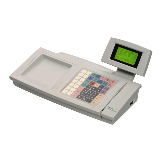
Page 8: Feature Locations
① KEYBOARD (FLAT or RAISED) ② MODE KEY ③ LCD ④ MCR ⑤ POWER(SMPS) ⑥ IRC ⑦ RS232 Serial I/F#4(RJ45) ⑧ RS232 Serial I/F#3(RJ45) ⑨ RS232 Serial I/F#2(DB9P Female) ⑩ RS232 Serial I/F#1(DB9P Female) ⑪ DRAWER Figure2-2 Feature Locations SAM4S ER-600 SERIES... -
Page 9: Power Specification
2-3-1 Power Specification Item Description Remark • AC 100-240V, 50-60Hz, 0.8A (Min : 90V, Max : 264V) Input Voltage & Current • Operating : 25W Power Consumption • DC 24V, 1.25A Output Voltage SMPS Output Table2-2 Power Specification SAM4S ER-600 SERIES... -
Page 10: Interface Specifications
• VCC(+5V/200mA) is supplied at 1in of RJ-45 Connector.(RS-232 #4) or other devices Table2-3 RS-232C Specification 2-4-1-(b) RS-232C I/F Cable FERRITE CORE : 1 Turn (OP-118E : 18.2×12.5×25.5) Figure2-3 RS-232C Cable(DB9P Female) Side User Spec RJ-45 Figure2-4 RS-232C Cable(RJ-45) SAM4S ER-600 SERIES... - Page 11 (F.G) 3 (RXD) 4 (TXD) 3 (RXD) 4 (TXD) HOST SIDE 6(CTS) SIDE 2 (DSR) 2 (DSR) 8 (DTR) 5(RTS) 8 (DTR) 7 (S.G) 7 (S.G) Figure 2-6 RS-232C Cable Connection(RJ-45) Note: F.G(Frame Ground) , S.G(Signal Ground) SAM4S ER-600 SERIES...
- Page 12 Then the host recognizes that the ECR is busy. So, the host does not transmit a data to the ECR. If the ECR is released from busy, the ECR transmits XON(ASCII 11h) to host through the Serial Data Line. Then the host recognizes that the ECR is not busy. And the host transmits a data to the ECR. SAM4S ER-600 SERIES...
- Page 13 Figure2-7 IRC Cable 2-4-2-(c) Cable Connection 1 (TX/RX_B) 1 (TX/RX_B) 2 (TX/RX_B) 2 (TX/RX_B) 3 (F.GND) 3 (F.GND) MASTER or SLAVE SLAVE 4 (F.GND) 4 (F.GND) 5 (TX/RX_A) 5 (TX/RX_A) 6 (TX/RX_A) 6 (TX/RX_A) Figure2-8 IRC Cable Connection SAM4S ER-600 SERIES...
- Page 14 Transmit/Receive Data Line A Pin 5 and Pin 6 are shorted each other on Main PCB. 6(12) TX/RX_A In/Out Table2-6 IRC Signal Description Note] The signal description of the Port#2 is same as it of the Port#1 SAM4S ER-600 SERIES...
-
Page 15: System Configuration
3 Installation and Operation 3-1 System Configuration 3-1-1 Configuration Figure 3-1 System Configuration Figure 3-2 IRC Terminator Note] The termination resistor 120[Ohm] must be installed at Host ECR and Last Slave ECR(S7). SAM4S ER-600 SERIES... -
Page 16: Installation
SRAM 12MBITs (4MBITs * 3) On Main PBA Table 3-1 Option 3-2-3 Supplies Item Description Remark Cable Tie 2 EA Ferrite Core RING-TR29A : 1 EA Mode Key VD, REG, X, Z, P, C User Manual 1 EA Table 3-2 Supplies SAM4S ER-600 SERIES... -
Page 17: Operation
Void, Off, Register, Manager, Clear Totals(Z) Void, Off, Register, Manager, Clear Totals, Program(PGM) Void, Off, Register, Manager, Clear Totals, Program, Service Mode(SM) Table3-4 Key Function Note] The Key can be removed from the key lock in the OFF or REGISTER(REG) position. SAM4S ER-600 SERIES... -
Page 18: All Clear
3. Press and hold the ‘CHECK’ key on key board and turn on the power switch at the same time. 4. When the buzzer beeps, press ‘PLU1’, ‘PLU7’, ‘CLERK#’, and ‘CASH Enter’ in sequence. RAM ALL CLEAR SERV. <-<-<-<- RAM1:OK RAM2:OK RAM3:OK RAM4:OK SUCCESS Figure3-6 Clear Display SAM4S ER-600 SERIES... - Page 19 8. Select the ‘Program Code only’. 9. Click ‘OK’ 10. Wait for about three minutes. 11. Turn off the power switch. 12. Remove the serial cable 13. Perform the all clear function Figure3-7 Download Window (Boot & Program) SAM4S ER-600 SERIES...
-
Page 20: Self Test
4. Press ‘0’~’4’ key consecutively. 3. If test operates normally, the message (‘OK’) is displayed on LCD and the Buzzer beep. Then Press “Clear” key. Note] When the ports are no connection or the cable is open, the Error happens. SAM4S ER-600 SERIES... -
Page 21: Disassembly And Assembly
6. After removing the two screws(C-2), lift up the ASS’Y SWITCH ROTARY(reference:C-3). Remove the two screws(C-1) and separate BRKT MODE(C-4) from the SWITCH ROTARY(C-3). 7. Remove the five screws(C-5) and separate the MAIN BOARD(C-6) from the CASE LOWER(C-16). Note]To assemble, reverse the procedure of disassembly. SAM4S ER-600 SERIES... - Page 22 4-4 Disassembling Diagram A. ASS'Y CASE-UPPER D. ASS'Y KBD(RAISED) E. ASS'Y KBD(FLAT) A-10 B. ASS'Y DISPLAY B-3 B-4 C-2 C-3 C-10 C. ASS'Y CASE-LOWER C-11 C-13 C-14 C-12 C-15 C-19 C-16 C-18 C-17 Figure4-1 Total Disassembly and Assembly SAM4S ER-600 SERIES...
-
Page 23: Reference Information
A10/P3.2 P8.1/TA4IN/U A9/P3.1 P8.2//INT0 P8.3//INT1 A8/P3.0 P8.4//INT2 P8.5/NMI A7/P2.7 A6/P2.6 A5/P2.5 A4/P2.4 XOUT A3/P2.3 /RESET A2/P2.2 P8.6/XCOUT A1/P2.1 P8.7/XCIN A0/P2.0 CNVSS /INT5/D15/P1.7 BYTE /INT4/D14/P1.6 P9.0/TB0IN/CLK3 /INT3/D13/P1.5 P9.1/TB1IN/RXD3/SCL3 D12/P1.4 P9.2/TB2IN/TXD3/SDA3 D11/P1.3 P9.3/DA0/TB3IN/CTS3 D10/P1.2 P9.4/DA1/TB4IN/CTS4 D9/P1.1 P9.5/ANEX0/CLK4 D8/P1.0 P9.6/ANEX1/TXD4/SDA4 SAM4S ER-600 SERIES... - Page 24 DRAWER SENSOR COMP2 P5.2 READ SIGNAL P10.2 DRAWER SENSOR COMP1 P5.1 P10.1 RTC_SDA P5.0 WRITE SIGNAL AVSS Ground P4.7 CHIP SELECT SIGNAL0 P10.0 ADC_BATVOLT P4.6 CHIP SELECT SIGNAL1 VREF P4.5 CHIP SELECT SIGNAL2 AVCC P4.4 ADDRESS20 P9.7 RXD4_IRC SAM4S ER-600 SERIES...
- Page 25 Control logic Address Inputs ~I/O Data Inputs/Outputs Power Ground Figure 5-1 SRAM KM684000 Specification BYTE# DQ15/A-1 DQ14 DQ13 DQ12 RESET# 48-P in TSOP— S tandard P in out DQ11 RY/BY# DQ10 Figure 5-2 Flash ROM AM29F800 Specification SAM4S ER-600 SERIES...
- Page 26 CS1CS2 CS3 A2 A1 A0 Y0 Y1 Y2 Y3 Y4 Y5 Y6 Y7 INPUTS ACTIVE–LOW OUTPUTS CHIP– PIN 16 = V CC SELECT PIN 8 = GND INPUTS H = high level (steady state); L = low level (steady state); X = don’t care FUNCTION TABLE Figure 5-6 74HC138 SAM4S ER-600 SERIES...
- Page 27 Figure 5-8 74HC541 FUNCTION TABLE Inputs Output NONINVERTING DATA Clock OUTPUTS INPUTS L,H, No Change X = Don’t Care Z = High Impedance CLOCK PIN 20 = V PIN 10 = GND OUTPUT ENABLE Figure 5-9 74HC574 SAM4S ER-600 SERIES...
- Page 28 FSOUT Frequency Scaling Description FS781 1x Modulated Frequency of Input Clock FS782 2x Modulated Frequency of Input Clock FS784 4x Modulated Frequency of Input Clock Table 2. FSOUT SSCG (Modulated Output Clock) Product Selection Figure 5-11 SSCG FS781 Specification SAM4S ER-600 SERIES...
- Page 29 DELAY CAPACOTOR Switch Sense Emitter Timing Capacitor Comparator Inverting SUPPLY VOLTAGE Input (T o p V iew) Figure 5-12 KA393 Figure 5-13 KA34063 Figure 5-14 M51953 INTRB(1) VDD(5) SCL(2) OSCIN(6) SDA(3) OSCOUT(7) VSS(4) INTRA(8) Figure 5-15 RS5C372A SAM4S ER-600 SERIES...
- Page 30 1. Emitter 2. Base 3. Collector [KSA1010-Y] [KSD288-Y] [KSA708-Y] SOT-23 SOT-23 SOT-23 1:A node 2:N.C 3:C athode 1:B ase 2:E mitter 3:C ollector 1:B ase 2:E mitter 3:C ollector [KSA1182-Y] [MMBT2222A] [MMBD6050] Figure 5-15 Transistor & Diode SAM4S ER-600 SERIES...
-
Page 31: Special Circuit Descriptions
Storage Circuit [For Battery Voltage] MAIN PWB Figure 6-1 Power Block Diagram Voltage Description VDRV (+24VDC) Cash Drawer Solenoid Driving (+5VDC) Logic IC Driving / VFD Filament Voltage (+Min 3.6VDC) Battery Voltage Table 6-1 Power Source Voltage Descriptions SAM4S ER-600 SERIES... - Page 32 L40 store energy. The voltage is smoothed by C79(470uF) and then +5Vdc Logic voltage is produced . 6-1-3 VBT : +Min 3.6Vdc VBT Battery Voltage is charged through D14(SK14). The Source Voltage is VCC(5V). When AC Power is off, VBT is supplied to SRAM, RTC for saving the data. SAM4S ER-600 SERIES...
-
Page 33: Reset Circuit
170Vac(Europe) . That is, when +24Vdc goes down to +14Vdc. VDRV 100nF 6.8K 3.3K 4.7K U15:1 LM393D VDRV_COMP VDRV_COMP INT0_PFAIL if, VDRV •Ó•§•£ 8V •¦‹} ""LOW" 4.7uF 100nF 1.2K [24V Power Fail Detect] Figure 6-2 Power Fail Detect Circuit SAM4S ER-600 SERIES... -
Page 34: Battery Circuit
The Buzzer is used to inform several kinds of states which occur under system operating and gives some information to users by controlling the P8.0 pin of CPU. The frequency of buzzer is 2[KHz] VDRV •ß‰Z•Ó‹÷ PASS •c (Peak 66V s 24V) MMBD6050LT1 MMBT2222A BUZZER 4.7K BUZZER Figure 6-5 Buzzer Circuit SAM4S ER-600 SERIES... - Page 35 Caution: Make sure that the Cash Drawer solenoid resistance is more than 20Ω VDRV DIODE-M4 MMBT2222A DRAWER1_OUT 4.7K DRAWER_1 KSD288 VDRV DIODE-M4 MMBT2222A DRAWER2_OUT 4.7K DRAWER_2 KSD288 Figure 6-6 Cash Drawer Block Circuit SAM4S ER-600 SERIES...
- Page 36 HOST checks whether the ECR is BUSY. Note] This is a RS232C H/W Handshaking Waveform between ECR and PC. RS-232C H/W Handshaking method is different between ECR and other peripheral and terminal equipment. Figure 6-8 RS-232C Waveform SAM4S ER-600 SERIES...
- Page 37 TX/RX_B Transmission a data (1 Byte) RECEIVE ACTION(ECR) (+)Level (5V) TX/RX_A (+)Level (5V) TX/RX_B A-B = A-B = A-B = A-B = A-B = (-)Level (+)Level (-)Level (+)Level (-)Level Received data (1 Byte) Figure 6-9 IRC Waveform SAM4S ER-600 SERIES...
-
Page 38: Keyboard Circuit
ADDRESS DECODER (74HC138) KBD_CS DATA[0:7] ADDRESS DECODER(74HC138) DIODE( MMBD6050L *16) Pull-Up • • 74HCT541 • 98 KEYS • • • • • • • COMMON PORT • • • • • MODE KEY Figure 6-10 Keyboard Block Diagram SAM4S ER-600 SERIES... -
Page 39: Troubleshooting
3. Check the VDRV signal whether it is short. Power VCC (+5V) Ok? 1. Check the IC34063(U26) 2. Check the TR 1010 (Q14) 3. Check Generated Frequency 4. Check the VCC whether it is short or open. SAM4S ER-600 SERIES... -
Page 40: System Problem
1. Check the nCS, nRD, nWR signal of SRAM SRAM Ok? 2. Check the VBT(Battery Volt.). 3. Check the Decoder IC 74HC138 (U9). 4. Replace the SRAM. 1. Check the VBT(Battery Volt.). RTC Ok? 2. Check the RTC Clock 32.768KHz 3. Replace the RTC(RS5C372A) SAM4S ER-600 SERIES... -
Page 41: Key Board Problem
Specific Key 2. Check the Matrix Bus & Data Bus Failure? 3. Check the Diodes 4. Check the Key Board Assy 1. Check the Harness & Mode Key Assy Mode Key 2. Check the 74HCT541 & Data Bus SAM4S ER-600 SERIES... - Page 42 2. Check the Tx,Rx Pin on I/F PBA. Failure ? 1. Check the connection of the IRC Connector and Other side. Communication 2. Check the IRC Cable whether it is open or short. Failure? 3. Check whether Signal is affected by the Cable Noise. SAM4S ER-600 SERIES...
-
Page 43: Exploded Views And Parts List
8-1 Main Set 8-1-1 Exploded View A. ASS'Y CASE-UPPER D. ASS'Y KBD(RAISED) E. ASS'Y KBD(FLAT) A-10 B. ASS'Y DISPLAY B-3 B-4 C-2 C-3 C-10 C. ASS'Y CASE-LOWER C-11 C-13 C-14 C-12 C-15 C-19 C-16 C-18 C-17 Figure8-1 Total Disassembly SAM4S ER-600 SERIES... -
Page 44: Parts List
PMO-COVER CABLE,HIPS(V0) C-10 JK72-20045A PMO-COVER WIRE,HIPS(V0) C-11 6002-000147 SCREW-TAPPING,PH,+,2,M3,L10,ZPC(YEL) C-12 JK70-50015A SCREW-MACHINE,BH,+,2,M2,L6,ZPC(BLK) C-13 JK75-20001A MEC-HINGE ASS'Y,ER-600 C-14 JK70-50015A SCREW-MACHINE,BH,+,2,M2,L6,ZPC(BLK) C-15 JK39-00008A CBF-HARNESS POWER S/W,ER-600 C-16 JK72-20040A PMO-CASE-LOWER,HIPS(V0) C-17 6002-000147 SCREW-TAPPING,PH,+,2,M3,L10,ZPC(YEL) C-18 JK68-40010A LABEL(P)-RATING,TETRON PAPER T0.05 C-19 JK61-40902A FOOT-RUBBER,TN-5630T SAM4S ER-600 SERIES... - Page 45 Remark JK59-30008G UNIT-KEYBOARD,NUMERICAL,ER-600R,USA JK59-30008H UNIT-KEYBOARD,DEPARTMENT,ER-600R,STD JK59-30008C UNIT-KEYBOARD,NUMERICAL,ER-600R,EUROPE JK59-30008D UNIT-KEYBOARD,NUMERICAL,ER-600R,ENGLAND JK59-30008E UNIT-KEYBOARD,NUMERICAL,ER-600R,SPAIN JK59-30008F UNIT-KEYBOARD,NUMERICAL,ER-600R,GERMANY JK81-10945A KEY-CAP(S),1X1 LABEL-KEY TOP,1X1 JK81-10947A KBD KEY-TOP(S) ASS'Y,1X1,LOW PROFILE JK81-10285T SPRING RETURN JK81-10946A KEY-CAP(L),1X2 JK81-10948A KBD KEY-TOP(L) ASS'Y,1X2,LOW PROFILE JK81-20001A SPRING RETURN,1X2 JK81-20009A KBD-HOUSING SAM4S ER-600 SERIES...
- Page 46 Remark JK81-10933A KEY-TOP,1 JK81-10934A KEY-TOP,2 JK81-10935A KEY-TOP,3 JK81-10936A KEY-TOP,4 JK81-10937A KEY-TOP,5 JK81-10938A KEY-TOP,6 JK81-10939A KEY-TOP,7 JK81-10940A KEY-TOP,8 JK81-10941A KEY-TOP,9 JK81-10942A KEY-TOP,0 JK81-10943A KEY-TOP,00 JK81-10944A KEY-TOP,● D-10 JK81-20010A KBD FPC ASSY D-11 JK81-20011A KBD FRAME D-12 JK81-20005A SCREW-TAPTITE,M2.6X6 SAM4S ER-600 SERIES...
- Page 47 Remark JK59-30010A UNIT-KEYBOARD,NUMERICAL,ER-600F,USA JK73-20214A REX-WATER-PROOF,ER-600F JK68-40009A LABEL(P)-KEYBOARD NUMERICAL,ER-600F,USA JK68-40009B LABEL(P)-KEYBOARD NUMERICAL,ER-600F,EUROPE JK68-40009C LABEL(P)-KEYBOARD NUMERICAL,ER-600F,ENGLAND JK68-40009D LABEL(P)-KEYBOARD NUMERICAL,ER-600F,SPAIN JK68-40009E LABEL(P)-KEYBOARD NUMERICAL,ER-600F,GERMANY JK68-40009F LABEL(P)-KEYBOARD DEPT,ER-600F,STD JK81-20009B KBD-HOUSING,ER-600F JK81-20012A KBD KEY-RUBBER,49KEY JK81-20010B KBD FPC ASS'Y,ER-600F JK81-20011B KBD FRAME,ER-600F JK81-20005A SCREW-TAPTITE,M2.6X6 SAM4S ER-600 SERIES...
- Page 48 8 Exploded Views and Parts List MEMO SAM4S ER-600 SERIES...
- Page 49 9 PCB Layout and Parts List 9-1 Main PCB Layout 9-1 Component Side View (PCB:JK41-10549A) SAM4S ER-600 SERIES...
-
Page 50: Main Pcb Layout
CORE-FERRITE BEAD:AA,-,3.5x0.6x6.5mm,-,- L1,L40,L49,L50 2001-001291 R-CARBON: 1OHM,5%,1/2W,AA,TP,3.5X9.5MM 2001-000855 R-CARBON:560OHM,5%,1/4W,AA,TP,2.4X6.4MM R87,R88 2005-001001 R-WIRE WOUND:0.1ohm,5%,1W,AA,TP,3.3x9mm 0403-000141 DIODE-ZENER:1N4735A,6.2V,5%,1W,DO-41,TP ZD1,ZD2,ZD3,ZD4 0403-000161 DIODE-ZENER:1N4751,5%,1000MW,DO-41,TP 0202-000216 SOLDER-BAR:S63S-B20,S63S,350X34,SN63/PB3 MAIN PCB 0202-001025 SOLDER-WIRE FLUX:KS-611,-,-,-,spray MAIN PCB 0204-000469 THINNER:#4662,-,0.795,- MAIN PCB JC68-10564A LABEL(P)-PROTECTOR:SLB-3108H,ART,-,100(S ROM LABEL JK96-10021A ELA ETC-HEAT SINK:KSA1010Y,H18mm SAM4S ER-600 SERIES... - Page 51 3301-000317 CORE-FERRITE BEAD:AB,2x1.25x0.9mm,-,- L12,L13,L14,L15,L16 3301-000317 CORE-FERRITE BEAD:AB,2x1.25x0.9mm,-,- L17,L18,L19,L20,L21 3301-000317 CORE-FERRITE BEAD:AB,2x1.25x0.9mm,-,- L22,L23,L24,L25,L26 3301-000317 CORE-FERRITE BEAD:AB,2x1.25x0.9mm,-,- L27,L28,L29,L30,L31 3301-000317 CORE-FERRITE BEAD:AB,2x1.25x0.9mm,-,- L32,L33,L34,L35,L36 3301-000317 CORE-FERRITE BEAD:AB,2x1.25x0.9mm,-,- L41,L42,L43,L44,L45 3301-000317 CORE-FERRITE BEAD:AB,2x1.25x0.9mm,-,- L46,L47,L48 2007-000300 R-CHIP:10KOHM,5%,1/10W,DA,TP,2012 R1,R2,R3,R5,R7 2007-000300 R-CHIP:10KOHM,5%,1/10W,DA,TP,2012 R8,R9,R10,R12,R13 2007-000300 R-CHIP:10KOHM,5%,1/10W,DA,TP,2012 R14,R15,R24,R48,R51 SAM4S ER-600 SERIES...
- Page 52 C25,C27,C33,C38,C41 2203-000192 C-CERAMIC,CHIP:100nF,+80-20%,50V,Y5V,TP, C42,C46,C50,C52,C56 2203-000192 C-CERAMIC,CHIP:100nF,+80-20%,50V,Y5V,TP, C57,C58,C62,C68,C71 2203-000192 C-CERAMIC,CHIP:100nF,+80-20%,50V,Y5V,TP, C72,C77,C81,C82,C83 2203-000192 C-CERAMIC,CHIP:100nF,+80-20%,50V,Y5V,TP, C84,C87,C88,C89,C90 2203-000938 C-CERAMIC,CHIP:0.47nF,5%,50V,NP0,TP,2012 C7,C11,C12,C16,C23 2203-000938 C-CERAMIC,CHIP:0.47nF,5%,50V,NP0,TP,2012 C28,C34,C35,C39,C43 2203-000938 C-CERAMIC,CHIP:0.47nF,5%,50V,NP0,TP,2012 C48,C51,C53,C59,C70 2203-000938 C-CERAMIC,CHIP:0.47nF,5%,50V,NP0,TP,2012 C75,C76 2203-000990 C-CERAMIC,CHIP:1uF,+80-20%,25V,Y5V,TP,20 C8,C9,C10,C17,C18 2203-000990 C-CERAMIC,CHIP:1uF,+80-20%,25V,Y5V,TP,20 C24,C26,C29,C30,C32 2203-000990 C-CERAMIC,CHIP:1uF,+80-20%,25V,Y5V,TP,20 C40,C44,C45,C47,C49 2203-000990 C-CERAMIC,CHIP:1uF,+80-20%,25V,Y5V,TP,20 C55,C61,C64,C67,C73 SAM4S ER-600 SERIES...
- Page 53 C78,C80 2203-000595 C-CERAMIC,CHIP:0.22nF,5%,50V,NP0,TP,2012 2203-000239 C-CERAMIC,CHIP:0.1nF,5%,50V,NP0,TP,2012 C91,C92 0202-000108 SOLDER-CREAM:RMA-010 T-322,S63,-,- MAIN PCB 0402-000129 DIODE-RECTIFIER;1N4003,200V,1A D36, D37 JK92-01235A PBA MAIN –BOARD:ER-600,EASYCASH,STD,4M JK92-01235B PBA MAIN –BOARD:ER-600,EASYCASH,CRS,4M JK92-01235C PBA MAIN –BOARD:ER-600,EASYCASH,STD,8M JK92-01235D PBA MAIN –BOARD:ER-600,EASYCASH,STD,12M JK92-01235E PBA MAIN –BOARD:ER-600,EASYCASH,STD,16M JK41-10549A PCB-MAIN:ER-600,EASYCASH,FR-4,2L,T1.6mm SAM4S ER-600 SERIES...
- Page 54 9 PCB Layout and Parts List MEMO SAM4S ER-600 SERIES...
-
Page 55: Block Diagram
10 Block Diagram 10-1 ER-600 SAM4S ER-600 SERIES 10-1... - Page 56 10 Block Diagram MEMO 10-2 SAM4S ER-600 SERIES...
-
Page 57: Wiring Diagram
SIGNAL NAME CN10(pin NO.2) CE3(192*64) DSR2 DSR3 nRESET MCR_RDT1&2 TXD2 TXD3 VOUT MCR_RCL1&2 RXD2 RXD3 MCR_CLS1&2 Short NO.8 short NO.8 BACKLIGHT VOL MCR_RDT2&3 Short NO.2 Short NO.2 MCR_RCL2&3 MCR_CLS2&3 DTR2 DTR3 CN1=MODE KEY CN12=SMPS CN3/4/11/14=KEYBOARD CN15=SWITCH SAM4S ER-600 SERIES 11-1... - Page 58 11 Wiring Diagram 11-2 Wiring Diagram Figure11-1 Wiring Diagram 11-2 SAM4S ER-600 SERIES...
-
Page 59: Schematic Diagrams
2) Memory, RTC, Decoder Block --------------------------------- 12-3 3) Power Control Block --------------------------------------------- 12-4 4) Serial I/F Block----------------------------------------------------- 12-5 5) Key & Mode S an Block ----------------------------------------- 12-6 6) Display (LCD) I/F Block ----------------------------------------- 12-7 7) Power Block -------------------------------------------------------- 12-8 SAM4S ER-600 SERIES 12-1... - Page 60 12-2 SAM4S ER-600 SERIES...
- Page 61 SAM4S ER-600 SERIES 12-3...
- Page 62 12-4 SAM4S ER-600 SERIES...
- Page 63 SAM4S ER-600 SERIES 12-5...
- Page 64 12-6 SAM4S ER-600 SERIES...
- Page 65 SAM4S ER-600 SERIES 12-7...
- Page 66 12-8 SAM4S ER-600 SERIES...
-
Page 67: Update Log
Use this page to record any special servicing information such as Service Bulletins or Supplements. When possible, record changes to Code numbers directly on the actual Parts List. Always record Service Bulletin numbers and Application Dates on this log to ensure that your data is always as current as possible. SAM4S ER-600 SERIES... - Page 68 Shin Heung Precision . FEBRUARY 2004 ⓒ Printed in KOREA. V1.1 Code No. : JK68-60935A...
Need help?
Do you have a question about the ER-600 and is the answer not in the manual?
Questions and answers