Sam4s ER-5100 Service Manual
Electronic cash register
Hide thumbs
Also See for ER-5100:
- Service manual (90 pages) ,
- Programming & operating manual (92 pages) ,
- Operator's and programming manual (7 pages)
Table of Contents
Advertisement
SERVICE
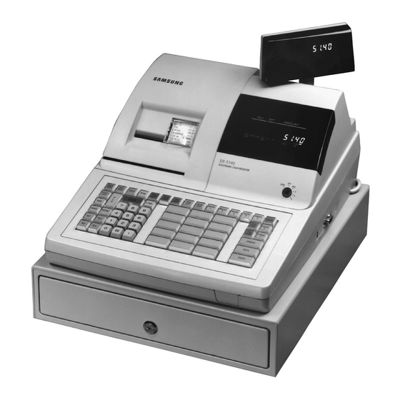
ELECTRONIC CASH REGISTER
ELECTRONIC CASH REGISTER
ER-5100 / ER-5140
ER-5115 / ER-5140FP
Manual
1.
Precaution Statements
2.
Product Specifications
3.
Installation and Operation
4.
Disassembly and Assembly
5.
Alignment and Adjustment
6.
Troubleshooting
7.
Exploded Views and Parts List
8.
PCB Parts List
9.
Block Diagram
10. Wiring Diagram
11. ASIC SCR60K Pin Assignment
12. Schematic Diagrams
C O N T E N T S
Advertisement
Table of Contents


Need help?
Do you have a question about the ER-5100 and is the answer not in the manual?
Questions and answers