Ruckus R510 - Access Point Manual
- User manual (152 pages) ,
- Quick start manual (4 pages) ,
- Quick setup manual (5 pages)
Advertisement
- 1 Introduction
- 2 Before You Begin
- 3 Package Contents
- 4 Step 1: Collecting Setup Requirements, Hardware and Tools
- 5 Step 2: Connecting Your Computer to the AP
- 6 Step 3: Preparing Your Computer for AP Setup
- 7 Step 4: Logging Into the AP
- 8 Step 5: Customizing the Wireless Settings
- 9 Step 6: Placing the AP in Your Site
- 10 Step 7: Verifying the Installation
- 11 Mounting Instructions
- 12 Documents / Resources
Introduction
This Quick Setup Guide provides step-by-step instructions on how to set up your Ruckus Wireless R510 Dual Band 802.11ac Multimedia Wi-Fi Access Point. After completing the steps described in this Guide, you will be able to place the Access Point (AP) at your site and provide wireless network access to users.
NOTE: The R510 requires a minimum of ZoneDirector version 9.13 or later, or SmartZone firmware version 3.4 or later.
Before You Begin
Before deploying Ruckus products, please check for the latest software and the release documentation.
- Release Notes and other user documentation are available at http://support.ruckuswireless.com/documents.
- Software upgrades are available at http://support.ruckuswireless.com/software.
- Open source information is available at http://opensource.ruckuswireless.com.
- Software license and limited warranty information are available at http://support.ruckuswireless.com/warranty.
NOTE: The minimum software revision for the T305i is SmartZone (SZ) 5.1.1 New AP Model.
Package Contents
A complete R510 installation package includes all of the items listed below:
- R510 Access Point
- One wall-mount anchor kit, including two 1" No. 8 steel panhead Phillips sheet metal screws, one 5mm M2.5 x 1.06 Torx security screw, and wall-mount anchors
- One external T-bar bracket (two unassembled parts)
- One unit removal pin
- Regulatory flyer
- Product warranty statement
- Declaration of Conformity, if required
- This Quick Setup Guide
Step 1: Collecting Setup Requirements, Hardware and Tools
- A computer running Windows 7 (procedures for other OS's are similar)
- Two Cat 5e Ethernet cables
- No. 2 Phillips screwdriver and T8 Torx driver for wall mounting anchor kit
- An AC power adapter (sold separately), or
- an 802.3af or 802.3at -compliant Power over Ethernet (PoE) switch or PoE injector
- When mounting the R510 to a truss or pole, two customer-supplied cable ties

If the AP is deployed with a ZoneDirector, then refer to the ZoneDirector Quick Setup Guide and connect the AP to your local network.
Step 2: Connecting Your Computer to the AP

- After removing your Ruckus AP from its package, place it next to your computer.
- Using an Ethernet cable, connect your computer's network port to one of the two ports on the AP.
- Using an AC adapter (sold separately), connect the AP 12VDC port to a protected power source. Alternatively, connect the PoE port to a PoE injector or switch for both power and network connections
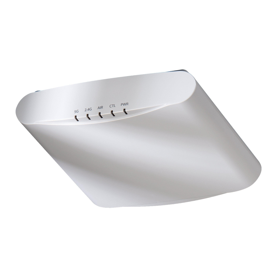
- Verify that the Power LED on the external enclosure is slowly flashing green.

- Reset button
- PoE Port
- 12V DC Port

The reset button is accessible using a thin wire, for example: a paperclip.
- To soft reset, single press the reset button.
- To factory reset the AP, press and hold the reset button for more than 3 seconds.
DO NOT RESET THE AP TO FACTORY DEFAULT SETTINGS UNLESS SO INSTRUCTED. (Doing this resets the AP IP address to 192.168.0.1.)
Step 3: Preparing Your Computer for AP Setup
NOTE: The following procedures assume Windows as the operating system. Procedures for other operating systems are similar.
- On your Windows PC, configure your network adapter from the Local Area Connection settings as follows:
Start > Control Panel > Network and Sharing Center > Change Adapter Settings - Edit the TCP/IPv4 address settings as follows:
Local Area Connection > Properties > Internet Protocol Version 4 (TCP/IPv4) > Properties
The Internet Protocol Version 4 (TCP/IPv4) Properties dialog box appears.
![]()
Write down all of the currently active settings so you can restore your computer to its current configuration later (when this process is complete). - Select Use the following IP address (if it is not already selected) and then make the following entries:
- IP address: 192.168.0.22 (or any available address in the 192.168.0.x network, except 192.168.0.1)
- Subnet mask: 255.255.255.0
- Default gateway: 192.168.0.1
Leave the DNS server fields empty.
- Click OK to save your changes. Your changes are put into effect immediately.
Step 4: Logging Into the AP
- As specified in Step 3, the admin PC should be directly connected to the AP through one of the Ethernet ports and powered on, ready for setup.
- On your admin PC, open a web browser window.
- In the browser, enter the following URL in the browser navigation bar:
https://192.168.0.1 - Press Enter to initiate the connection. When the security alert dialog box appears, click OK/Yes to proceed.
- When the Ruckus Admin login page appears, enter the following:
- Username: super
- Password: sp-admin
- Click Login. On your first login, you will be prompted to change the default password.
- When the Change Password dialog box displays, enter the following:
- New Password: Enter a new password.
- Confirm Password: Re-enter the new password.
- Click Submit.
- Log in using the new password.
Step 5: Customizing the Wireless Settings
TABLE 1
Default AP Settings (for your reference)
| Network Names (SSIDs) | Wireless1—Wireless8 (2.4GHz radio) Wireless9—Wireless16 (5GHz radio) |
| Security (Encryption method) | Disabled for each wireless interface |
| Default Management IP Address | 192.168.0.1 |
- On the web interface menu, click Configuration > Radio 2.4G or Configuration > Radio 5G. The Configure > Wireless > Common page appears.
- Verify that the following options are active:
Channel : SmartSelect
Country Code: If you are not located in the United States of America, select your current country. - Click Update Settings if you made any changes.
- Click any of the Wireless # (Wireless LAN Number) tabs at the top of the page.
- In Wireless Availability, click Enabled.
- Delete the text in the SSID field, then type a name for your network that will help your users identify this AP in their wireless network application.
- Click Update Settings to save your changes.
- Repeat for each Wireless # (Wireless LAN Number) interface that you want to enable.
- Click Logout to exit the web interface.
- When the Ruckus Admin login page reappears, you can exit your browser.
- Disconnect the AP from the computer and from the power source, and then restore your computer to its original network connection configuration settings.
Step 6: Placing the AP in Your Site
- Move the AP to its permanent location (accessible to both power and network connections). Refer to the Mounting Instructions section for physical installation.
- Use an Ethernet cable to connect the POE port to an appropriate device:
- The ISP's or carrier's network device.
- An Ethernet switch that is connected to the ISP's or carrier's network device.
- Connect the AP power adapter (or PoE power supply) to the AP, and then to a convenient power source.
NOTE: If you will be using PoE, then you will need a Cat 5e (or better) Ethernet cable to connect the AP to the PoE switch or PoE injector. - Verify that the POE port LED is lit.
After a short pause to re-establish the Internet connection, you can test the AP.
Step 7: Verifying the Installation
- Using any wireless-enabled computer or mobile device, search for and select the wireless network you previously configured.
- When connected, open a browser and connect to any public website.
Congratulations! Your wireless network is active and ready for use.
Mounting Instructions
Mounting on a Flat Surface
The factory-supplied mounting screws and plastic wall anchors allow you to attach the AP to a wall or other flat surface.

- Use the Mounting Template on the last page of this Quick Setup Guide to mark the locations for two drill holes on the mounting surface.
- Use a 4.75mm (3/16") drill bit to drill holes approximately 25mm (1") deep into the mounting surface.
- Insert the factory-supplied anchors and mounting screws into the mounting surface, leaving approximately 6 mm (1/4") of the screw heads protruding for the AP enclosure.
- To remove the AP, insert the unit removal pin into the hole on the top of the AP to unlock, then push the AP up to release the AP enclosure from the mounting screws.
Mounting on a Drop-Ceiling T-Bar
NOTE: This mounting bracket can also be used on a flush drop-ceiling T-bar, so the four rubber feet on the bottom of the AP minimize ceiling tile displacement.
The enclosed T-bar bracket allows you to attach the AP to recessed drop-ceiling T-bars.
Mounting an AP using the External Bracket
- Position the studs on the bottom of the T-bar bracket (B in the Figure below) in the mounting holes on the AP enclosure, and then slide the T-bar bracket until the studs are in the narrow parts of the AP mounting keyholes. The mounting bracket locks in place on the AP enclosure.

- Attach the locking tab (C) to one side of the T-bar and the bracket (B) to the other side of the T-bar.
- Slide the locking tab (C) into the bracket (B) so that it locks in place around the T-bar (Figure below). Make sure that both clasps are gripping the T-bar.


Removing an External Bracket from a T-Bar

- Move the ceiling tiles out of the way.
- Slide the locking tab away from the T-bar to release the AP-bracket assembly from the T-bar.
- The AP-and-T-bar bracket assembly comes away from the T-bar.
Removing the External Bracket from the AP

- Insert the unit removal pin into the hole on the front of the AP to unlock the mounting bracket from the AP enclosure.
- Slide the mounting bracket toward the Ethernet ports on the AP until it detaches from the AP.
Mounting on a Flush Drop-Ceiling T-Bar
Mounting an AP using the Integrated T-bar clips
NOTE: The built-in mounting clips on the bottom of the AP are designed to accommodate 15/16 T-bar widths only.
- Orient the AP so that the T-bar is positioned between the T-bar clips as shown in Figure below, then rotate the AP until the third T-bar clip catches the T-bar and the latch locks the T-bar in place.


- Torx screw hole
- Insert the Torx security screw into the hole near the latch to lock the AP in place.
- To remove the AP from a T-bar, first remove the security screw, then depress the latch while rotating the AP so that the T-bar clips disengage the T-bar.


Mounting on a Truss or Pole
- Feed the customer-supplied cable ties through the four slots on the back of the AP.

- Cable tie slots
- Fasten the AP to the truss or pole using the cable ties.

Documents / Resources
References
![support.ruckuswireless.com]() Technical Documents | Ruckus Wireless Support
Technical Documents | Ruckus Wireless Support![support.ruckuswireless.com]() Software Downloads | Ruckus Wireless Support
Software Downloads | Ruckus Wireless Support![opensource.ruckuswireless.com]() Commscope, Inc. | ANS, CCS, NICS, OWN Products / Welcome to Commscope, Inc. | ANS, CCS, NICS, OWN Products
Commscope, Inc. | ANS, CCS, NICS, OWN Products / Welcome to Commscope, Inc. | ANS, CCS, NICS, OWN Products
Download manual
Here you can download full pdf version of manual, it may contain additional safety instructions, warranty information, FCC rules, etc.
Advertisement


Need help?
Do you have a question about the R510 and is the answer not in the manual?
Questions and answers