Table of Contents
Advertisement
Quick Links
Quick Install Guide
Use the AGS-1024 to:
Add 24 Gigabit Ports to Your AV Rack Solutions
„
Future Proof Your Network with Gigabit Speeds (10X
„
Performance of Fast Ethernet)
Set-up a Dedicated Network for Optimizing VoIP, Video,
„
Security, or Gaming Applications
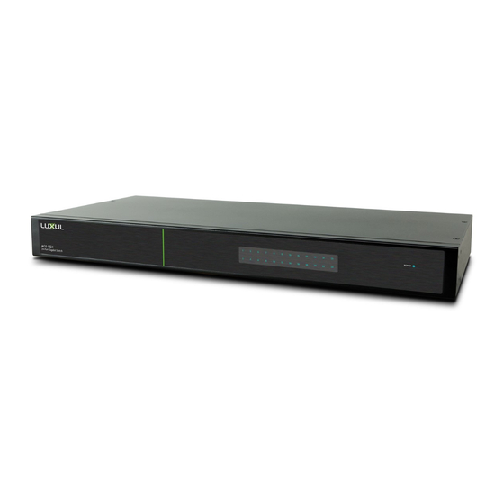
24-Port Gigabit Switch
Simply Connected
AGS-1024
Advertisement
Table of Contents

Related Manuals for Luxul AGS-1024


Summary of Contents for Luxul AGS-1024
-
Page 1: Quick Install Guide
Simply Connected Quick Install Guide AGS-1024 24-Port Gigabit Switch Use the AGS-1024 to: Add 24 Gigabit Ports to Your AV Rack Solutions „ Future Proof Your Network with Gigabit Speeds (10X „ Performance of Fast Ethernet) Set-up a Dedicated Network for Optimizing VoIP, Video, „... -
Page 2: Document Conventions
No part of this publication may be modified or adapted in any way, for any purposes without permission in writing from Luxul. The material in this manual is subject to change without notice. Luxul reserves the right to make changes to any product to improve reliability, function, or design. No license is granted, either expressly or by implication or otherwise under any Luxul intellectual property rights. -
Page 3: Package Contents
AGS-1024 for return/replacement. HARDWARE DESCRIPTION Front Panel The front panel of the AGS-1024 Switch includes 24 (1 for each port) dual colored Link/Activity LEDs that can be switched from green to blue. In addition, the front panel has a single Power LED. -
Page 4: Led Indicators
AGS-1024 Quick Install Guide LED Indicators The front panel LEDs of the AGS-1024 include 1 Power indicator and 24 numbered Link/Activity indicators. These LEDs show the operating status of the AGS-1024 and each switch connection. LED Indicators The following chart shows the LED indicators of the AGS-1024 along with an explanation of the indicator’... -
Page 5: Preparing For Installation
Ensure there is suffi cient space around the AGS-1024 for proper ventilation and „ heat dissipation. It is recommended to have at least 4-6 inches around all sides. When installing the AGS-1024 on a surface, attach the rubber feet to the bottom „ of the device to avoid scratching the surface. -
Page 6: Desktop Setup
AGS-1024 INSTALLATION Installing the AGS-1024 in a Rack The AGS-1024 can easily be installed in a standard 19” rack. The AGS-1024 includes two mounting ears for installing and stabilizing the switch. When attaching the mounting ears and installing the switch within a rack, please refer to the following illustration: Rack-Mounting the AGS-1024 Using the included screws, attach the mounting ears to each side of the switch. -
Page 7: Connecting To A Router Or Other Switch
Connecting to a Router or Other Switch Connecting the AGS-1024 to Router or Switch When a device is properly connected, the Link/Activity LED for each port lights up. Please refer to the LED Indicators section for indicator defi nitions and troubleshooting. -
Page 8: Fcc Statement
This device complies with part 15 of the FCC Rules. Hereby, Luxul, 14203 Minuteman Drive, Suite 201, Draper, Utah, 84020, declares that this Luxul AGS-1024 is in compliance with the essential requirements and other relevant provisions of Directive 1999/5/EC. For a copy of this report send a self addressed stamped envelope to: Luxul CE, 14203 Minuteman Drive, Suite 201, Draper, Utah, 84020.
Need help?
Do you have a question about the AGS-1024 and is the answer not in the manual?
Questions and answers