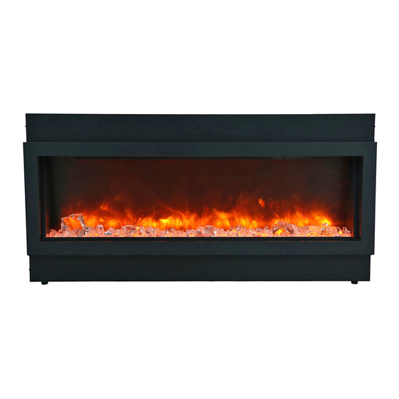
Amantii BI-40-DEEP Installation And Operation Instructions Manual
Hide thumbs
Also See for BI-40-DEEP:
- Installation and operation instructions manual (29 pages) ,
- Installation and operation instructions for (21 pages) ,
- Installation & owner's manual (35 pages)
Summary of Contents for Amantii BI-40-DEEP
- Page 1 INSTALLATION AND OPERATION INSTRUCTIONS FOR BUILT- IN UNITS BI-40-DEEP BI-50-DEEP BI-60-DEEP BI-72-DEEP BI-88-DEEP 09 13-01...
- Page 2 TABLE OF CONTENTS...
-
Page 3: Important Instructions
IMPORTANT INSTRUCTIONS WARNING! 5. Do not use outdoors. grounded Cover Of Grounded Outlet Box Metal Screws Grounding Pin Adapter Grounding Means Grounding Fig. 1 SAVE THESE INSTRUCTIONS... - Page 4 BI-40-DEEP Built Volta e 1500W 1500W 750W NOTE: This appliance must be electrically wired and grounded in accordance with local codes. In the absence o cal codes, us the current CSA C22.1 Canadian Elec- trical Code in Canada or the ANSI/NFPA States.
- Page 5 BI-50-DEEP Built Volta e 1500W 1500W 750W NOTE: This appliance must be electrically wired and grounded in accordance with local codes. In the absence o cal codes, us the current CSA C22.1 Canadian Elec- trical Code in Canada or the ANSI/NFPA States.
- Page 6 BI-60-DEEP Built Volta e 1500W 1500W 750W NOTE: This appliance must be electrically wired and grounded in accordance with local codes. In the absence o cal codes, us the current CSA C22.1 Canadian Elec- trical Code in Canada or the ANSI/NFPA States.
- Page 7 BI-72-DEEP Built Volta e 1500W 1500W 750W NOTE: This appliance must be electrically wired and grounded in accordance with local codes. In the absence o cal codes, us the current CSA C22.1 Canadian Elec- trical Code in Canada or the ANSI/NFPA States.
- Page 8 BI-88-DEEP Built Volta e 1500W 1500W 750W NOTE: This appliance must be electrically wired and grounded in accordance with local codes. In the absence o cal codes, us the current CSA C22.1 Canadian Elec- trical Code in Canada or the ANSI/NFPA States.
-
Page 9: Installation Overview
INSTALLATION OVERVIEW NOTE: BEFORE YOU INSTALL SITE SELECTION all. re et o e all Power supply Wire Gage relat stalla- Voltage Wire Gage Fuse 5. Plug in the unit, then press the control buton on Wall switch / t hermostat Wire Gage Volta e 5 Volts re err... -
Page 10: Package Contents
PACKAGE CONTENTS Description Quantity Picture Part Screw 0.16 in. x 1.0 in. Wall Plug 0.3 in. x 1.5 in. Wood Screw 0.16 in. x 0.6 in. -
Page 11: Hard-Wire Installation
HARDWIRE INSTRUCTIONS Wall 1. Ma e sur re er al outlet. HARD-WIRE INSTALLATION 1. Unscrew two screw show in the below. Remove the cover plate and the power cord fix piece, remove power cord. Remove the knockout. 2. Attach the wiring to the junction block WARNING: outlets or r . -
Page 12: Installation-Built In
NOTE: The optional trim can be pull out directly from the unit. It will need two person to do it. The rough wall opening size of the fireplace. W(") D(") H(") BI-40-DEEP BI-50-DEEP BI-60-DEEP BI-72-DEEP BI-88-DEEP... - Page 13 INSTALLATION- BUILT IN...
- Page 14 1. Take off the front clear glass. There is a bracket which hold the front glass. It is show as left. Unscrew the screw and take off the bracket. Turn around and insert to the gap It can hook the glass and pull out the glass. 2.
-
Page 15: Operating The Unit
OPERATING THE UNIT DISPLAY ON/OFF DISPLAY ORANGE DISPLAY BLUE HEATER ON/OFF HIGH TEMP. - Page 16 1. Heat control button 2. Flame control button Plug the heater into a suitable outlet. 1) “Heat control button” Press the HEAT button repeatedly to set the heater to the desired heat setting. The Heater will work on as shown below. HIGH / 1500W LOW / 750W AUTO MODE...
-
Page 17: Replacing The Remote Control Battery
REPLACING THE REMOTE CONTROL BATTERY When the remote control stops operating or its range seems reduced, it is time to replace the batteries with new ones. Remove the batteries if the remote control won’t be used for a long period of time. 1. -
Page 18: Care And Maintenance
CARE AND MAINTENANCE CLEARANCE TO COMBUSTIBLES Keep electrical cords, drapery, furniture and other combustibles at least 3 ft. from the front of the heater and away from the sides. CLEANING TRIM Clean the metal trim using a soft cloth, slightly dampened with a citrus oil-based product and buff with a clean soft cloth. -
Page 19: Fireplace Maintenance
FIREPLACE MAINTENANCE WARNING: er be ore e or to r e the ris LED LIGHT BULB REPLACEMENT ht bulbs are to be r rer t’s ser WARNING: UNIT DISPOSAL stes. T re e to the e o trolle te the... -
Page 20: Troubleshooting
TROUBLE SHOOTING WARNING Disconnect power before performing any maintenance and allow to cool before servic- SYMPTOM POSSIBLE CAUSES CORRECTIVE ACTION loose. Replace AA batteries in remote control. If problem persists, ther er t sible r er ailure rat- or r erheat to ool t h t... - Page 21 REF NO. PART NO. DESCRIPTION REMAKR 1 602030C BLOWER AND HEATER ASSEMBLY FRT60420 2 601089E CIRCUIT BOARD LRC9-05 3 301506 REMOTE RECEIVER 4 601140 LED STRIP FOR FLAME AND EMBER LED-H20-1 5 601141 LED STRIP FOR FLAME AND EMBER LED-H30-1 10105048 REMOTE 7 10101201C...
-
Page 22: Service History
SERVICE HISTORY This heat st be ser Dealer service technician Date service Performed special Concerns Name Name NOTES:... -
Page 23: Warranty
WARRANTY...


Need help?
Do you have a question about the BI-40-DEEP and is the answer not in the manual?
Questions and answers