
Related Manuals for NXP Semiconductors T2080RDB-PC


Summary of Contents for NXP Semiconductors T2080RDB-PC
- Page 1 QorIQ T2080 Reference Design Board (T2080RDB-PC) User Guide Document Number: T2080RDBPCUG Rev. 0, 04/2016...
- Page 2 QorIQ T2080 Reference Design Board (T2080RDB-PC) User Guide, Rev. 0, 04/2016 Freescale Semiconductor, Inc.
-
Page 3: Table Of Contents
Ethernet controllers ................................21 Ethernet Management Interface............................22 I2C....................................23 2.10 SPI interface ...................................24 2.11 Local bus..................................25 2.12 SDHC interface................................25 2.13 USB interface..................................26 2.14 RS-232.................................... 27 2.15 JTAG/COP port................................28 QorIQ T2080 Reference Design Board (T2080RDB-PC) User Guide, Rev. 0, 04/2016 Freescale Semiconductor, Inc. - Page 4 3.1.10 Miscellanies control and status register (MISCCSR)..................42 3.1.11 Boot configuration override register (BOOTOR)....................43 3.1.12 Boot configuration register 1 (BOOTCFG1)..................... 43 3.1.13 Boot configuration register 2 (BOOTCFG2)..................... 43 QorIQ T2080 Reference Design Board (T2080RDB-PC) User Guide, Rev. 0, 04/2016 Freescale Semiconductor, Inc.
-
Page 5: Related Documentation
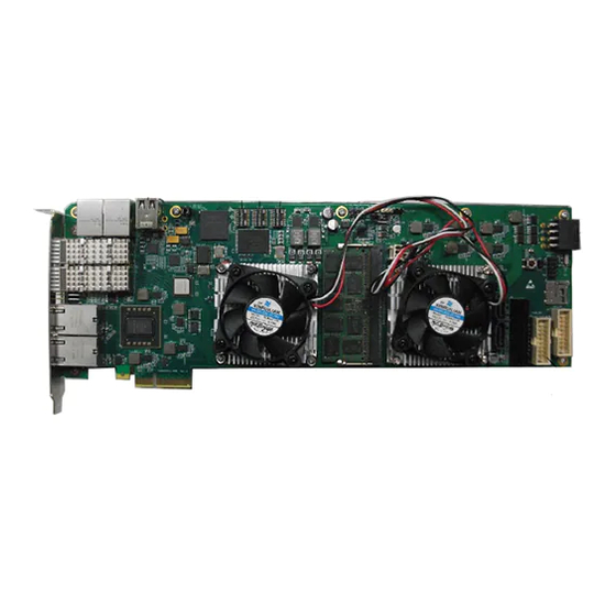
SerDes ports. This system has two working modes, the Standalone mode and the PCIe Endpoint mode. The motherboard, inside the T2080RDB-PC, is a PCIe form factor card and it is installed in a custom 1U chassis. The system will be in standalone mode by default and you can remove the PCIe from its chassis for PCIe Endpoint mode operation. -
Page 6: Acronyms And Abbreviations
Serial Advanced Technology Attachment Secure Digital SerDes Serializer/Deserializer SGMII Serial Gigabit Media Independent Interface Serial Peripheral Interface Switch SYSCLK System Clock Table continues on the next page... QorIQ T2080 Reference Design Board (T2080RDB-PC) User Guide, Rev. 0, 04/2016 Freescale Semiconductor, Inc. -
Page 7: T2080 Silicon Features
• Up to four 10 Gbit/s Ethernet MACs • Up to eight 1 Gbit/s Ethernet MACs • Up to four 2.5 Gbit/s Ethernet MACs • IEEE 1588 standard support. • High-speed peripheral interfaces: QorIQ T2080 Reference Design Board (T2080RDB-PC) User Guide, Rev. 0, 04/2016 Freescale Semiconductor, Inc. -
Page 8: T2080Rdb-Pc Board Features
• NOR: 16 bit, non-multiplexed, up to 128 MB, NOR devices support 8 virtual banks • Ethernet • Two on-board RGMII 10/100/1G Ethernet ports • Two on-board XFI 10GEDC for 10G SFP+ Port • Two on-board XFI 10GBase-T port QorIQ T2080 Reference Design Board (T2080RDB-PC) User Guide, Rev. 0, 04/2016 Freescale Semiconductor, Inc. -
Page 9: Block Diagram
• Two I2C ports 1.5 Block diagram The T2080RDB-PC supports two modes of operation, the Standalone mode and the Endpoint mode. There is one configuration in the Standalone mode and second configurations is in the Endpoint mode, the major differences are in the PCIe support. All configurations have Freescale C293, 4x XFI, 2x RGMII, DDR, NOR, NAND, SPI EEPROM, I2C EEPROM, and GPIO. - Page 10 2 x USB2.0 w/PHY 8 lanes up to 10 GHz SerDes 8 lanes up to 8 GHz SerDes Clocks/reset GPIO CCSR Figure 1-1. T2080 block diagram QorIQ T2080 Reference Design Board (T2080RDB-PC) User Guide, Rev. 0, 04/2016 Freescale Semiconductor, Inc.
- Page 11 Local Bus (8bit) MT29F8G08ABABAWP-12IT (1GB) TXD,RXD,RTS,CTS RJ45 MAX3232 SPI FLASH TXD,RXD,RTS,CTS SPI Bus RJ45 MAX3232 N25Q512A13GSF40F (64MB) SDHC Bus Micro SD card Figure 1-2. T2080RDB-PC architecture QorIQ T2080 Reference Design Board (T2080RDB-PC) User Guide, Rev. 0, 04/2016 Freescale Semiconductor, Inc.
- Page 12 Block diagram QorIQ T2080 Reference Design Board (T2080RDB-PC) User Guide, Rev. 0, 04/2016 Freescale Semiconductor, Inc.
-
Page 13: Architecture
2.2 Power The power supply system of the T2080RDB-PC system uses power from a standard 6-pin EPS, to provide power to the numerous processors, CPLD, and peripheral devices. QorIQ T2080 Reference Design Board (T2080RDB-PC) User Guide, Rev. 0, 04/2016... - Page 14 • All power supplies can be sequenced as per hardware specifications The power supplies provided are organized into general categories and are described in the individual sections. The diagram below shows the power supply architecture. QorIQ T2080 Reference Design Board (T2080RDB-PC) User Guide, Rev. 0, 04/2016 Freescale Semiconductor, Inc.
- Page 15 SN74LVCIGS6(U7/9/11) SFPX2(J13/J15) SN74LVC1GS6(U7/9/11) ICS843002(U47) Y66.66MHz(X3) MICX11(U67) T2080 sys refclk USB: MIC2506(U24) Y133.33MHz(X4) MAX3232(U27) T2080 ddr refclk DSI339U(U31) Y24MHz(x1) Usb_refclk AT24C256(U33) ADT7481(U34) LDT9FGV0641 Figure 2-1. Power supply QorIQ T2080 Reference Design Board (T2080RDB-PC) User Guide, Rev. 0, 04/2016 Freescale Semiconductor, Inc.
-
Page 16: Reset
Clocks 2.3 Reset Reset signals to and from the T2080 processor and other devices on the T2080RDB-PC are managed by CPLD. The diagram below shows an overview of the reset architecture. CPLD EC1_RST_N RGMII GE PHY1 EC2_RST_N PEX4_RST_N RGMII Golden finger... -
Page 17: Ddr
ICS843002 SD1_REFCLK1_P/N(156.25MHz) SD1_REFCLK1_P/N PEX4_REFCLK_P/N(100MHz) Golden finger SD1_REFCLK2_P/N(100MHz) PI3PCIE3212 SD1_REFCLK2_P/N SD2_REFCLK1_P/N SD2_REFCLK2_P/N PEX_CLK_P/N(100MHz) SD2_REFCLK1_P/N(100MHz) SD2_REFCLK2_P/N(100M) IDT9FGV0641 PEX4S_REFCLK_P/N(100M) C290_SD_REFCLK_P/N(100M) C293 25MHz C290_SYSCLK (66.66MHz) OSC-66.66MHz Figure 2-3. Clock architecture QorIQ T2080 Reference Design Board (T2080RDB-PC) User Guide, Rev. 0, 04/2016 Freescale Semiconductor, Inc. -
Page 18: Serdes Port
IR3475 51200 IV35 Figure 2-4. Memory interface 2.6 SerDes port The T2080 SerDes block provides 16 high-speed serial communication lanes, supporting a variety of protocols, including: QorIQ T2080 Reference Design Board (T2080RDB-PC) User Guide, Rev. 0, 04/2016 Freescale Semiconductor, Inc. - Page 19 XFI1 XFI2 PCIe4 1111 2222 SERDES2 SRDS_PRTCL_S2 Per lane PLL mapping PCIe1 PCIe PCIe SATA 1111 1122 The image below shows the SerDes distribution of T2080RDB-PC. QorIQ T2080 Reference Design Board (T2080RDB-PC) User Guide, Rev. 0, 04/2016 Freescale Semiconductor, Inc.
-
Page 20: Pci Express Support
PCle x 4 Gen3 support Figure 2-5. SerDes distribution of T2080RDB-PC 2.6.1 PCI Express support The T2080RDB-PC supports PCIe x4 Gen 3 for golden finger and PCIe x4 Gen 2 for slot. 2.6.2 XFI 10G optics port support The T2080 supports evaluation of the XFI protocol using Cortina CS4315 dual port 10G CDR. -
Page 21: Xfi 10Gbase-T Port Support
2.7 Ethernet controllers The T2080 supports two Ethernet Controllers (EC), which can connect to Ethernet PHYs using MII or RGMII protocols. On the T2080RDB-PC, the EC1 and EC2 ports only operates in RGMII mode. Both ports connect to Realtek RTL8211 PHYs. -
Page 22: Ethernet Management Interface
However, EMI2 is only used with XFI based PHYs, which uses 1.2 V pull-up. EMI1 is used with all other non-XFI based PHYs, including the onboard RGMII PHYs. The image below shows the EMI hardware block. QorIQ T2080 Reference Design Board (T2080RDB-PC) User Guide, Rev. 0, 04/2016 Freescale Semiconductor, Inc. - Page 23 The T2080 devices supports up to four I2C buses, in order to make the I2C resources equally available to both local and remote systems. The T2080RDB-PC uses I2C1 port to access onboard devices, such as DDR3 DIMM, RTC, I2C EEPROM, clock generator, thermal sensor (ADT7481), and core power regulator (IR36021).
-
Page 24: Spi Interface
SFP+ optics Channel 1 I2C2_SFP2_SDA 0x50 I2C2_SCL I2C2 PCA9546 I2C2_SDA I2C2_CHAN2_SCL NOT USE Channel 2 I2C2_CHAN2_SDA I2C2_PEX4S_SCL PCle SLOT I2C2_PEX4S_SDA Channel 3 I2C_ADDR-0X77 Figure 2-10. I2C subsystem QorIQ T2080 Reference Design Board (T2080RDB-PC) User Guide, Rev. 0, 04/2016 Freescale Semiconductor, Inc. -
Page 25: Local Bus
Chapter 2 Architecture 2.10 SPI interface The T2080RDB-PC Serial Peripheral Interface (SPI) pins is only used for onboard SPI device accessing various SPI memory devices. 2.11 Local bus The T2080 Integrated Flash Controller (IFC), also known as the local bus, supports 32-bit addressing and 8 or 16-bit data widths for a variety of devices to effectively manage all these resources with the maximum amount of performance and flexibility. -
Page 26: Usb Interface
USB interface On T2080RDB-PC, a single connector is used for MicroSD memory cards, as shown in the image below. Clamping diodes SD_WP SD_CD T2080 SDHC_CLK Micro SD Card DAT[0:3] DAT[0:3] Figure 2-12. SDHC interface 2.13 USB interface The T2080RDB-PC systems have two integrated USB 2.0 controllers, that allow direct connection to USB ports with appropriate protection circuitry and power supplies. -
Page 27: Rs-232
The T2080 processor has two UART controllers, which provides an RS-232 standard interconnection between the board and an external host. The serial connection is typically configured to run at 11.5 Kbit/s. QorIQ T2080 Reference Design Board (T2080RDB-PC) User Guide, Rev. 0, 04/2016 Freescale Semiconductor, Inc. -
Page 28: Jtag/Cop Port
• Data rate: 115200 bit/s • Number of data bits: 8 • Parity: None • Number of stop bits: 1 • Flow control: Hardware/None QorIQ T2080 Reference Design Board (T2080RDB-PC) User Guide, Rev. 0, 04/2016 Freescale Semiconductor, Inc. - Page 29 The 16-pin generic header connector carries the COP/JTAG signals and the additional signals for system debugging. The pin-out of this connector is shown in the image below. TRST_B VDD_SENSE CKSTP_IN SRESET_B HRESET_B CKSTP_OUT Figure 2-16. 16-pin connector QorIQ T2080 Reference Design Board (T2080RDB-PC) User Guide, Rev. 0, 04/2016 Freescale Semiconductor, Inc.
-
Page 30: Connectors, Headers, Jumper, Push Buttons, And Leds
Connectors, Headers, Jumper, Push buttons, and LEDs The table below displays the connections made from the T2080RDB-PC COP connector. Table 2-3. Connections made from the T2080RDB-PC COP connector Pin no. Signal name Connection Connected directly between the processor and JTAG/COP connector. -
Page 31: Headers
IR36021 Header Used for programming the IR36021. COP/JTAG Used for debugging the T2080. 2.16.3 Jumper The table below describes how the push Jumper is used on the T2080RDB-PC platform. Table 2-6. Jumper on the T2080RDB-PC platform Reference Description Status 1... -
Page 32: Push Buttons
1-2: TF card works at 3.3 V 2-3: TF card works at 1.8 V 2.16.4 Push buttons The table below describes what the push buttons are used for on the T2080RDB-PC platform. Table 2-7. Push buttons on T2080RDB-PC platform Reference designators... - Page 33 C Bus Thermal sensor T2080 ADT7481 DXP1 TEMP_ANODE DXN1 TEMP_CATHODE C29x TEMP_ANODE DXP2 DXN2 TEMP_CATHODE OVER ALARM ALERT/THERM2 THERM ALARM THERM FAN_Power CPLD Figure 2-17. Temperature QorIQ T2080 Reference Design Board (T2080RDB-PC) User Guide, Rev. 0, 04/2016 Freescale Semiconductor, Inc.
-
Page 34: Dip Switch Definition
DIP switch definition 2.18 DIP switch definition The T2080RDB-PC board has user selectable switches, for evaluating different boot configurations and other special configurations for this device. This configuration allows either the switch or the CPLD register to set the POR pin. The CPLD register allows software to override the pin remotely when the board is in the board farm. - Page 35 NOR flash is selected as boot flash (CS0 is connected to NOR flash by setting SW3[4] to ON, RCW[0:8] is set to 0_0111_xxxx using SW1[1:8] and SW2[1]), different U-Boot image can be selected to boot up the board, by setting SW3[5:7]. QorIQ T2080 Reference Design Board (T2080RDB-PC) User Guide, Rev. 0, 04/2016 Freescale Semiconductor, Inc.
- Page 36 DIP switch definition QorIQ T2080 Reference Design Board (T2080RDB-PC) User Guide, Rev. 0, 04/2016 Freescale Semiconductor, Inc.
-
Page 37: Cpld Specification
Boot configuration register 2 (BOOTCFG2) See section 3.1.13/43 3.1.1 Chip ID1 register (CHIPID1 ) Address: 0h base + 0h offset = 0h Read CHIPID1 Write Reset QorIQ T2080 Reference Design Board (T2080RDB-PC) User Guide, Rev. 0, 04/2016 Freescale Semiconductor, Inc. -
Page 38: Chip Id2 Register (Chipid2)
Address: 0h base + 2h offset = 2h Read HW_VER Write Reset HWVER field descriptions Field Description 0–7 The version field of the hardware board. HW_VER QorIQ T2080 Reference Design Board (T2080RDB-PC) User Guide, Rev. 0, 04/2016 Freescale Semiconductor, Inc. -
Page 39: Software Version Register (Swver)
1: Writing logic 1 will produce 10GBase-T PHY(AQ1202) reset# signal; this bit can auto clear. 0: No reset occurs PEX_RST 1: Writing logic 1 will produce PCIe x4 slot reset# signal; this bit can auto clear. QorIQ T2080 Reference Design Board (T2080RDB-PC) User Guide, Rev. 0, 04/2016 Freescale Semiconductor, Inc. -
Page 40: Flash Control And Status Register (Flhcsr)
1: NOR flash bank select bit2 set 1. 3.1.7 Thermal control and status register (THMCSR) Address: 0h base + 12h offset = 12h THM_ THM_ Read FAULT ALERT Reserved FAN_PWM Write Reset QorIQ T2080 Reference Design Board (T2080RDB-PC) User Guide, Rev. 0, 04/2016 Freescale Semiconductor, Inc. -
Page 41: Panel Led Control And Status Register (Ledcsr)
3.1.9 SFP+ control and status register (SFPCSR ) Address: 0h base + 14h offset = 14h SFP1_ SFP1_ SFP2_ SFP2_ Read SFP1_DET SFP2_DET SFP1_ SFP2_ RXLOS TXFAIL RXLOS TXFAIL TXDIS TXDIS Write Reset QorIQ T2080 Reference Design Board (T2080RDB-PC) User Guide, Rev. 0, 04/2016 Freescale Semiconductor, Inc. -
Page 42: Miscellanies Control And Status Register (Misccsr)
This field is reserved. 0: PCIe x4 card not present PEX_PRS 1: PCIe x4 card present 0: TEST_SEL_N pin status is 0 TEST_SEL_N 1: TEST_SEL_N pin status is 1 QorIQ T2080 Reference Design Board (T2080RDB-PC) User Guide, Rev. 0, 04/2016 Freescale Semiconductor, Inc. -
Page 43: Boot Configuration Override Register (Bootor)
Manual (document T2080RM). 3.1.13 Boot configuration register 2 (BOOTCFG2) Address: 0h base + 18h offset = 18h Read cfg_rcw_ Reserved cfg_svr[0:1] Reserved cfg_eng_use[0:2] Write src8 Reset QorIQ T2080 Reference Design Board (T2080RDB-PC) User Guide, Rev. 0, 04/2016 Freescale Semiconductor, Inc. - Page 44 RCW source bit 8. cfg_rcw_src8 This field is reserved. 2–3 cfg_svr bits for Power-on Reset using. cfg_svr[0:1] This field is reserved. 5–7 cfg_eng_use bits for Power-on Reset using. cfg_eng_use[0:2] QorIQ T2080 Reference Design Board (T2080RDB-PC) User Guide, Rev. 0, 04/2016 Freescale Semiconductor, Inc.
-
Page 45: Revision History
Revision history The table below summarizes revisions to this document. Table A-1. Revision history Revision Date Topic cross-reference Change description Rev. 0 06/2015 Initial public release. QorIQ T2080 Reference Design Board (T2080RDB-PC) User Guide, Rev. 0, 04/2016 Freescale Semiconductor, Inc. - Page 46 QorIQ T2080 Reference Design Board (T2080RDB-PC) User Guide, Rev. 0, 04/2016 Freescale Semiconductor, Inc.
- Page 47 How to Reach Us: Information in this document is provided solely to enable system and software implementers to use Freescale products. There are no express Home Page: or implied copyright licenses granted hereunder to design or fabricate freescale.com any integrated circuits based on the information in this document. Web Support: Freescale reserves the right to make changes without further notice to any products herein.
Need help?
Do you have a question about the T2080RDB-PC and is the answer not in the manual?
Questions and answers