Table of Contents
Advertisement
Quick Links
Freescale Semiconductor
User Guide
TWR-56F8200 Tower Board
1 Overview
The MC56F8200 Tower System 32-bit MCU
module (TWR-56F8200) is an evaluation,
demonstration and development board. The
TWR-56F8200 can operate standalone or as the
main control board in a Tower system with
peripheral modules. It can also be used as the
main control board with an
APMOTOR56F8000E motor control board.
The following list summarizes the features of
the TWR-56F8200:
32-bit Digital Signal Controller module
featuring MC56F82748 in a 64-LQFP
package
Tower system compatible
Selectable power sources:
o USB on 56F8200 card
o Barrel connector on 56F8200
card
o Motor control board plug
direct to 56F8200 card, no
Tower System connection,
plug motor control to 9 V.
o Tower System elevator board
(USB or Barrel on Primary
side)
© 2013 Freescale Semiconductor, Inc.
_______________________________________________________________________
Document Number: TWR56F8200UG
Contents
1
Overview ................................................... 1
2
Hardware features ..................................... 3
3
Jumper table ............................................ 15
4
Getting started ......................................... 18
5
Revision history ...................................... 35
6
connector pin functions ................................... 35
7
schematic......................................................... 38
8
38
9
layout (top view) ............................................. 43
layout (bottom view) ....................................... 44
Rev 1, 10/2013
Advertisement
Table of Contents

Related Manuals for NXP Semiconductors freescale TWR-56F8200


Summary of Contents for NXP Semiconductors freescale TWR-56F8200
-
Page 1: Table Of Contents
Freescale Semiconductor Document Number: TWR56F8200UG User Guide Rev 1, 10/2013 TWR-56F8200 Tower Board 1 Overview The MC56F8200 Tower System 32-bit MCU Contents module (TWR-56F8200) is an evaluation, demonstration and development board. The Overview ........... 1 TWR-56F8200 can operate standalone or as the Hardware features ........ - Page 2 Filtered power for VDDA and VSSA on the 32-bit MC56F82748DSC Optional 8 MHz crystal circuit for the MC56F82748 DSC Nine LEDs controlled by the MC56F82748 DSC Two trimmer potentiometers for user to change analog input voltage ...
-
Page 3: Hardware Features
Tower Elevator Expansion Connectors 5.0V 3.3V (SPI, I2C, ADC, FEC, TPM, SCI, KB, etc.) External Connectors From an engineering perspective, the measuring instrument is controlled by legally relevant and legally Barrel Power Connector non-relevant software applications (see Error! Reference source not found.). Motor Control&... - Page 4 2.1 Tower system MCU module The TWR-56F8200 board is an MCU module designed for standalone use (or with a Freescale Tower system) and complies with the electrical and mechanical specification as described in Freescale Tower Electromechanical Specification [1]. Connection to the Tower system is through two expansion card- edge connectors that interface to the Elevator boards in a Tower system: the Primary and Secondary Elevator connectors.
- Page 5 the P5V_TRG_USB power net out of the USB switch at U501, the P5V_ELEV power net from the elevator connection at J500 pins A1 and B1, or the PWR_IN power net from the 2mm barrel jack at J3 through resettable fuse F1. Table 6 shows the operation of the different shunt positions.
- Page 6 2.3.1 Clock sources for the MC56F82748 DSC Three options are available for clocking the MC56F82748 device: Oscillator internal to the MC56F82748 chip —approximately 8 MHz. 8 MHz crystal External clock input from Primary Tower Connector or the AUX Connector. The internal oscillator is used to clock the MC56F82748 MCU immediately following reset.
- Page 7 Pin# Connected signal Description Shunt pins 2 and 3 together to connect RXD_SEL from the USB bridge function on the OSBDM/OSJTAG the DSC RXD0 pin to the USB serial MCU. bridge function. Shunt pins 3 and 4 together to connect the DSC RXD1 pin to the USB serial bridge function.
- Page 8 As can be seen in the tables, the 56F82748 DSC serial signals may be connected to either the Tower serial signals or to the USB bridge chip; however, only one channel may be connected to the USB bridge chip. If the associated 56F82748 DSC serial pins are not being used for the serial functions, the shunts should be removed from those pins.
- Page 9 Some of the MC56F82748 DSC pins are connected to the motor control connector. The pins associated with analog inputs have 100 Ω resistors in series to provide some ESD protection for the analog inputs of the DSC. The pins providing analog signals from the motor control board have 2200 pF capacitors with the 100 Ω...
- Page 10 MC56F82748 DSC signal MC56F82748 DSC signal TCK/GPIOD2 GPIOE3/PWMA_1A TMS /GPIOD3 GPIOE2/PWMA_1B GPIOB3/ANB3&VREFLB&CMPC_IN0 GPIOE5/PWMA_2A/XB_IN3 (With 100 Ω in series) GPIOB4/ANB4&ANC12&CMPC_IN1 GPIOE4/PWMA_2B/XB_IN2 (With 100 Ω in series) GPIOB5/ANB5&ANC13&CMPC_IN2 GPIOA4/ANA4&ANC8&CMPD_IN0 (With 100 Ω in series) (With 100 Ω in series) GPIOB6/ANB6&ANC14&CMPB_IN1 GPIOA5/ANA5&ANC9 (With 100 Ω in series)(100K Trimpot in parallel) (With 100 Ω...
- Page 11 Pin # MC56F82748 DSC signal Pin # MC56F82748 DSC signal J502-11 GPIOF7/TB3/CMPC_O/SS1_B/XB_IN3 J502-12 GPIOC2/TXD0/TB0/XB_IN2/CLKO J502-13 GPIOF8/RXD0/TB1/CMPD_O J502-14 GPIOC5/DACO/XB_IN7 J502-15 GPIOC11/CANTX/SCL1/TXD1 J502-16 GPIOC7/SS0_B/TXD0 J502-17 GPIOC12/CANRX/SDA1/RXD1 J502-18 GPIOC8/MISO0/RXD0/XB_IN9 J502-19 J502-20 GPIOC9/SCK0/XB_IN4 J502-21 No Connection J502-22 GPIOC10/MOSI0/XB_IN5/MISO0 J502-23 No Connection J502-24 No Connection J502-25 No Connection J502-26...
- Page 12 electrostatic discharges and lowers the impedance of the analog signal so that it can be sampled with less noise. 2.3.8 CAN transceiver The TWR-56F8200 board has a CAN transceiver circuit that may be connected to the CAN pins of the DSC.
- Page 13 2.3.11 JTAG header and OSBDM/OSJTAG disconnect header The TWR-56F8200 board includes an OSBDM/OSJTAG circuit as a debug interface to the C56F82748 DSC for normal purposes. If the user desires to use a different debugger connection, header J14 provides a connection point for an external JTAG hardware debugger. If an external debugger is connected to the JTAG header, the shunts at J21 (pins 1 to 2, 3 to 4, 5 to 6, and 7 to 8) which connect the SBDM/OSJTAG circuit to the JTAG signals should be removed, allowing the external debugger to control the JTAG port, rather than the JM60.
- Page 14 2.4.3 Clocking the OSBDM/OSJTAG MCU (MC9S08JM60) The MC9S08JM60 MCU uses an onboard 4 MHz external crystal circuit (Y2, R16, C7, and C9) for its clock. There are no user options for clocking the MC9S08JM60 MCU. 2.4.4 Reserved function select header Header J20 selects whether the onboard MC9S08JM60 MCU operates as an OSBDM/OSJTAG debug interface or as a USB Serial Bridge interface on older versions of S08 firmware such as may have existed on prototypes of the TWR56F8200.
-
Page 15: Jumper Table
translators are high-impedance if the signal OUT_EN_B goes high. This happens if the OSBDM/OSJTAG circuit looses power (no power to the USB connector). In that case, the OUT_EN signal from the OSBDM/OSJTAG MCU (pin 15) is biased low by R12. The inverter at U502B then drives OUT_EN_B high in response. - Page 16 Power use Jumper Function Shunts Description case Connect ELEV_RXD0 from the Tower connector to MC56F82748 DSC pin GPIO /RXD0/TB1 Connect RXD_SEL from the USB Serial Bridge to MC56F82748 DSC pin GPIO /RXD0/TB1 Disconnect MC56F82748 DSC pin Pin 2 RXD Source Select (note that GPIO /RXD0/TB1 open...
- Page 17 Power use Jumper Function Shunts Description case open No CAN termination Connect the CAN transceiver TXD and RXD to MC56F82748 DSC pins GPIOC11/CANTX/SCL1/TXD1 CAN Enable 1-2, 3-4 GPIOC12/CANRX/SDA1/RXD1 open Disconnect the CAN transceiver Enable USB bootloading of the MCU Flash memory MC9S08JM60 Bootload Enable open Disable bootloading...
-
Page 18: Getting Started
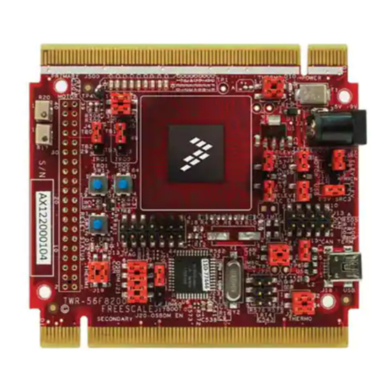
4 Getting started 4.1 Introduction In this section, you will find details that give step by step instructions on how to set up your Tower system for several different scenarios: Debugging new application on TWR-56F8200 using MultiLink o Set up a new project application interfacing with the Universal Multilink interface ... - Page 19 Figure 3. TWR-56F8200 tower board 4.3 Software installation After the hardware is configured, the software needs to be set up. The first step is for the user to set up CodeWarrior. You need to install CodeWarrior to program and debug the TWR-56F8200, and FreeMASTER for debugging via GUI.
- Page 20 4.4 Procedure for debugging new applications on TWR-56F8200 Using MultiLink Prerequisite: Download and install CodeWarrior Development Tools as mentioned in Software installation. 1. Connect jumpers on TWR-56F8200 module: Connect all the jumpers on 56F8200 board as mentioned in Table 6. 2.
- Page 21 2. Connect USB cable: Connect one end of the USB cable to the TWR-56F8200 board and other to the computer. 3. Create an application for MC56F82748: Launch CodeWarrior and run the program. a) From the menu, choose File > New > Bareboard Project. b) Assign a project name, such as “ProjDSC”...
- Page 22 2. Power to TWR-56F8200 TWR card: Power up the TWR-56F8200 board using the USB cable from the computer’s USB port. 3. Connect programming /debugging tool: Connect P&E Universal multilink to TWR-56F8200 at JTAG connector J14, and make sure the red wire of ribbon connector connects to Pin1 on J14. Connect the other end of the P&E Universal Multilink to computer USB port 4.
- Page 23 E0 and E1 will flash in intervals of 200 ms. All other LEDs will be turned off. The thermistors and the LEDs are related as shown in this table. Thermistor LEDs E0, E1 E2, E3 E4, E5 E6, E7 If you remove the finger from the thermistor, the LED will return to the default flash pattern. 4.7 Programming the Tower system with thermistor demo using OSBDM/OSJTAG Prerequisite: Download and Install CodeWarrior Development Tools as mentioned in...
- Page 24 e) A list of all the selected projects will appear. Select TWR56F8200_Thermistor_lab_JTAG and click “Copy projects into workspace” button and then click Finish. f) Choose Project > Clean to clean and build TWR56F8200_Thermistor_lab_JTAG project. Click the “Clean projects selected below” button and select TWR56F8200_Thermistor_lab_JTAG. Select “Start a build immediately”...
- Page 25 2. Power to TWR-56F8200 TWR card: Connect one end of the USB cable to the TWR-56F8200 board and the other to the computer for supplying power to the board. 3. Connect programming /debugging tool: Connect P&E Universal multilink to TWR-56F8200 at JTAG connector J14, and make sure red wire of ribbon connector connects to Pin1 on J14.
- Page 26 7. Assemble TWR-MC-LV3PH module: Connect the white edge of the TWR-MC-LV3PH module with the white edge of the primary Tower elevator. 8. Assemble TWR-56F8200 module: Connect the white edge of the TWR-56F8200 module with the white edge of the primary Tower elevator. 9.
- Page 27 4.9 Programming the Tower System with LV_Motor Demo using OSBDM/OSJTAG Prerequisite: Download and install CodeWarrior Development Tools as mentioned in Software installation. 1. Connect jumpers on TWR-56F8200 module: Reconfigure the TWR-56F8200 module by removing all jumpers. Reconnect the ten pins shown in diagrams below in red to first program the TWR-56F8200 stand alone with “MC56F82748_TWR_LV_BLDC”...
- Page 28 5. Connect jumpers on TWR-MC-LV3PH module: Reconfigure the TWR-MC-LV3PH module by removing all wires and jumpers. Reconnect the two pins shown in red in this figure. 6. Assemble TWR-MC-LV3PH module: Connect the white edge of the TWR-MC-LV3PH module with the white edge of the primary Tower elevator. 7.
- Page 29 4.10 LV_Motor Spin demo controlled via FreeMASTER using Universal Multilink Prerequisite: Download and install CodeWarrior Development Tools as mentioned in Software installation. 1. Connect jumpers on TWR-56F8200 module: Reconfigure the TWR-56F8200 module by removing all jumpers. Reconnect the 10 pins shown in red in the following figure to first program the TWR- 56F8200 standalone with “MC56F82748_TWR_LV_BLDC”...
- Page 30 5. Disconnect the computer and power: Remove the USB cable from the TWR-56F8200. Remove the P&E U-Multilink from TWR-56F8200. Click OK on the pop-up window which appears while disconnecting USB cable. 6. Connect jumpers on TWR-MC-LV3PH module: Reconfigure the TWR-MC-LV3PH module by removing all wires and jumpers.
- Page 31 13. Power the motor: Plug in the included 24-volt power supply. Apply the resulting 24 volts to the barrel connector of the TWR-MC-LV3PH module only. 14. Open FreeMASTER: In CodeWarrior, under MC56F82748_TWR_LV_BLDC, click the FreeMASTER folder. Double click the BLDC_HS_demo_TWR56F8400.pmp file. It will open the FreeMASTER application.
- Page 32 2. Click the RUN/STOP button to Run position and provide desired speed in “Required Speed” column 3. Click the Demo switch to “on” position. This will run the demo code and the motor will run by speed and direction that are predefined in the source code. 4.11 LV_Motor Spin demo controller via FreeMASTER using OSBDM/ OSJTAG Prerequisite: Download and install CodeWarrior Development Tools as mentioned in Software...
- Page 33 i) Select SDM_OSJTAG as the choice of hardware for debugging. j) In the Debug Configuration window, under the ‘main’ tab in the application, click “search project”, select MC56F82748_TWR_LV_BLDC.elf and click OK. k) Click Debug on the right bottom of the window to load the program. l) After the program loads, it will stop in the main program.
- Page 34 10. Connect the motor and the power: Connect the motor three-prong cable to the three-prong connection on the TWR-MC-LV3PH. Connect the motor five-prong cable to the five-prong connection on the TWR-MC-LV3PH. The green wires of both cables will be on the inside, facing each other. 11.
-
Page 35: Revision History
15. Make the connection: On the Menu bar of FreeMASTER, click the STOP button. The status of FreeMASTER at rightmost corner must change from NOT CONNECTED to a display showing the connection details. 16. Adjust the motor speed: The motor can now be controlled via the graphical user interface shown on screen. - Page 36 3.3V_1 3.3V Power 3.3V_4 3.3V Power (must not be connected) ELE_PS_SENSE_1 3.3V_5 3.3V Power GND_2 Ground GND_10 Ground GND_3 Ground GND_11 Ground SDHC_CLK / SPI1_CLK SCK (see also pin B48) I2C0_SCL SCL0 SDHC_D3 / SPI1_CS1_b I2C0_SDA SDA0 GPIO9/UART1_CTS SDHC_D3 / SPI1_CS0_b SS_B (see also pin B46) GPIOA4/ANA4 B10 SDHC_CMD / SPI1_MOSI MOSI (see also pin B45)
- Page 37 ELEV_RXD0 (see CAN0_RX0 CANRX UART0_RX also pin B61) ELEV_TXD0 (see CAN0_TX0 CANTX UART0_TX also pin B62) 1WIRE UART1_RX ELEV_RXD1 SPI0_MISO/IO1 MISO (see also pin B11) UART1_TX ELEV_TXD1 SPI0_MOSI/IO0 MOSI (see also pin B10) VSSA SPI0_CS0_b SS_B (see also pin B9) VDDA SPI0_CS1_b CAN1_RX...
-
Page 38: Appendix B-Twr-56F8200 Board Schematic
7 Appendix B—TWR-56F8200 board schematic under the “Downloads” The schematic is available as a standalone pdf at: freescale.com/TWR-56F8200 tab then within the “Hardware Development Tools” section. 8 Appendix C—TWR-56F8200 board BOM Reference Description Mfg. name Mfg. part number C1,C2,C506,C516,C520,C54 CAP CER 10UF 16V 10% 0805YD106KAT 0,C541 X5R 0805... - Page 39 LED AMBER SGL 25MA AVAGO HSMA-C190 0603 TECHNOLOG DIODE ZNR 200W 12V SOD- SMF12AT1G Semiconductor D500 DIODE SCH PWR RECT 1A MBR130LSFT1 30V SOD-123 Semiconductor D501 DIODE SCH DUAL CC Fairchild BAT54C 200MA 30V SOT23 FUSE PLYSW 1.1A 0.48 TYCO SMD100F-2 OHM SMT ELECTRONIC...
- Page 40 J500 CON DUAL 2X82 Edge PCI EDGE PCI Express SMT 1MM SP 591H EXPRESS 164 FOR TOWER SYSTEM NOT A PART TO ORDER J501 CON 2X20 SMT SKT 100MIL SAMTEC SSM-120-L-DV- CTR 307H AU J502 CON 2X13 SKT SMT 100MIL SAMTEC SSM-113-L-DV- CTR 300H AU...
- Page 41 R500,R501,R502,R503,R504 RES MF 330 OHM 1/16W 1% VISHAY CRCW0402330R ,R507,R556,R558,R559 0402 INTERTECH NOLOGY R505,R506 RES MF 158K 1/16W 1% KOA SPEER RK73H1ETTP15 0402 R508,R509,R562,R569,R571 RES MF 4.99K 1/16W 1% KOA SPEER RK73H1ETTP49 ,R576 0402 R510,R511,R512,R513,R514 RES MF 100 OHM 1/16W 1% THYE MING CR-02FL6--100R ,R515,R516,R517,R518,R51...
- Page 42 TP1,TP2,TP3,TP5,TP6 TEST POINT BLACK 40 MIL COMPONENT TP-105-01-00 DRILL 180 MIL TH 109L CORPORATI TEST POINT BLACK 40 MIL COMPONENT TP-105-01-00 DRILL 180 MIL TH 109L CORPORATI IC VREG LDO 3.3V 0.7A 4.3- LINEAR LT1129CST- 20V SOT-223 TECHNOLOG 3.3#PBF IC CTLER DSP 32BIT 2.7- FREESCALE PC56F82748ML 3.3V LQFP64...
-
Page 43: Appendix D-Twr-56F8200 Board Jack Layout (Top View)
U505 IC BUF QUAD TS 1.65-3.6V TEXAS SN74LVC125AP TSSOP14 INSTRUMEN XTAL 8.000MHZ SER SMT Citizen HCM49- 8.000MABJ-UT XTAL 4MHZ -- 18PF 20PPM ABRACON ABLS- CORP 4.000MHZ-B2-T 9 Appendix D—TWR-56F8200 board jack layout (top view) TWR-56F8200 Tower Board, Rev. 1, 10/2013 Freescale Semiconductor Inc. -
Page 44: Appendix E-Twr-56F8200 Board Jack Layout (Bottom View)
10 Appendix E—TWR-56F8200 board jack layout (bottom view) with TWR-56F8200 Tower Board, Rev. 1, 10/2013 Freescale Semiconductor Inc. - Page 45 Information in this document is provided solely to enable system and software How to Reach Us: implementers to use Freescale products. There are no express or implied copyright licenses granted hereunder to design or fabricate any integrated circuits based on the Home Page: information in this document.
Need help?
Do you have a question about the freescale TWR-56F8200 and is the answer not in the manual?
Questions and answers