Table of Contents
Advertisement
Quick Links
UM11493
TEA2209DB1584 active bridge rectifier controller demo board
Rev. 1.1 — 6 April 2021
Document information
Information
Content
Keywords
TEA2209T, TEA2209DB1584, active bridge rectifier controller, X-capacitor
discharge, self-supplying, high efficiency, traditional diode bridge, power
supply, demo board
Abstract
The TEA2209T is an active bridge rectifier controller replacing the traditional
diode bridge. Using the TEA2209T with low-ohmic high-voltage external
MOSFETs significantly improves the efficiency of the power converter as the
typical rectifier diode-forward conduction losses are eliminated. In addition,
the TEA2209T includes an X-capacitor discharge function. To reduce power
consumption at a standby condition, an external signal via the COMP pin can
disable the TEA2209T. This user manual describes how the TEA2209DB1584
demo board can be used to replace the traditional diode bridge. This demo
board contains a TEA2209T and four low-ohmic high-voltage MOSFETs.
User manual
Advertisement
Table of Contents

Related Manuals for NXP Semiconductors GreenChip TEA2209DB1584


Summary of Contents for NXP Semiconductors GreenChip TEA2209DB1584
- Page 1 UM11493 TEA2209DB1584 active bridge rectifier controller demo board Rev. 1.1 — 6 April 2021 User manual Document information Information Content Keywords TEA2209T, TEA2209DB1584, active bridge rectifier controller, X-capacitor discharge, self-supplying, high efficiency, traditional diode bridge, power supply, demo board Abstract The TEA2209T is an active bridge rectifier controller replacing the traditional diode bridge.
- Page 2 UM11493 NXP Semiconductors TEA2209DB1584 active bridge rectifier controller demo board Revision history Date Description v.1.1 20210406 Updated version Modifications: • Figure 6 Section 5 has been updated. • Figure 9 Section 6.3 has been updated. 20210129 Initial version UM11493 All information provided in this document is subject to legal disclaimers.
-
Page 3: Introduction
UM11493 NXP Semiconductors TEA2209DB1584 active bridge rectifier controller demo board Introduction Note: This product has not undergone formal EU EMC assessment. As a component used in a research environment, it is the responsibility of the user to ensure that the finished assembly does not cause undue interference when used. -
Page 4: Features
UM11493 NXP Semiconductors TEA2209DB1584 active bridge rectifier controller demo board 1.1 Features • Elimination of forward conduction losses of the diode rectifier bridge • Very low IC power consumption (2 mW) • Integrated high-voltage level shifters • Directly drives four rectifier MOSFETs •... -
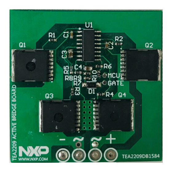
Page 5: Board Photographs
UM11493 NXP Semiconductors TEA2209DB1584 active bridge rectifier controller demo board Board photographs The TEA2209DB1584 demo board consists of the TEA2209T in an SO16 package with four MOSFETs (600 V; 28 mΩ). Figure 3 shows the front side of demo board. -
Page 6: Tea2209Db1584 Demo Board Setup
UM11493 NXP Semiconductors TEA2209DB1584 active bridge rectifier controller demo board TEA2209DB1584 demo board setup The TEA2209DB1584 demo board contains four 600 V/28 mΩ MOSFETs. It makes the board suitable for universal AC input and output power applications of several hundreds of Watts. - Page 7 UM11493 NXP Semiconductors TEA2209DB1584 active bridge rectifier controller demo board Figure 5 shows an example of the TEA2209DB1584 demo board mounted on an NXP Semiconductors TEA2016DB1519 demo board. Figure 5. TEA2209DB1584 demo board added to 240 W resonant adapter board UM11493 All information provided in this document is subject to legal disclaimers.
-
Page 8: Operation
UM11493 NXP Semiconductors TEA2209DB1584 active bridge rectifier controller demo board Operation The TEA2209T is a controller IC for an active bridge rectifier. It can directly drive the four MOSFETs in an active bridge. Figure 6 shows a typical configuration. As the output is a rectified sine wave, a boost-type power-factor circuit must follow the application. - Page 9 UM11493 NXP Semiconductors TEA2209DB1584 active bridge rectifier controller demo board Using a typical value of 2.2 μF for C yields about 0.24 s. While VR discharges the X-capacitor, the mains can be reconnected. In that case, the charge mode is entered again.
-
Page 10: Performance
UM11493 NXP Semiconductors TEA2209DB1584 active bridge rectifier controller demo board Performance 6.1 Test facilities • Oscilloscope: Agilent Technologies DSOX3034T • AC power source: Chroma 61504 • Electronic load: Chroma 63600-2 • Digital power meter: WT210 • Power board: TEA2016DB1519 6.2 Test setup To measure the system performance the TEA2209DB1584 is mounted on the TEA2016DB1519. - Page 11 UM11493 NXP Semiconductors TEA2209DB1584 active bridge rectifier controller demo board Figure 8. TEA2209T test setup on TEA2016DB1519 When the MOSFET pin open test for active bridge is required, add a diode in parallel to each active bridge MOSFET. To enable or disable active bridge operation via the COMP pin, the TEA2209T supports an external signal.
-
Page 12: Pol
UM11493 NXP Semiconductors TEA2209DB1584 active bridge rectifier controller demo board 6.3 Design guideline for COMP and COMP_POL The TEA2209T can disable gate drivers using an external signal. The external signal is connected to the COMP pin. Depending on the COMP_POL selection, either a high level or a low level on the COMP pin disables gate operation. -
Page 13: Start-Up Sequence
UM11493 NXP Semiconductors TEA2209DB1584 active bridge rectifier controller demo board 6.4 Start-up sequence After AC mains voltage is applied, the body diodes of the MOSFET rectifiers are connected until the TEA2209T is enabled. The internal self-bias circuit from the rectified mains voltage, VR, supplies the VCC. - Page 14 UM11493 NXP Semiconductors TEA2209DB1584 active bridge rectifier controller demo board CH1: AC mains (300 V/div) CH1: AC mains (300 V/div) CH2: VCC (5 V/div) CH2: VCC (5 V/div) CH3: GATELL (10 V/div) CH3: GATELL (10 V/div) CH4: COMP (5 V/div)
-
Page 15: Normal Operation
UM11493 NXP Semiconductors TEA2209DB1584 active bridge rectifier controller demo board CH1: AC mains (300 V/div) CH1: AC mains (300 V/div) CH2: VCC (5 V/div) CH2: VCC (5 V/div) CH3: GATELL (10 V/div) CH3: GATELL (10 V/div) CH4: COMP (2 V/div) - Page 16 UM11493 NXP Semiconductors TEA2209DB1584 active bridge rectifier controller demo board CH1: AC mains (300 V/div) CH1: AC mains (300 V/div) CH2: PFC gate from TEA2016 (5 V/div) CH2: PFC gate from TEA2016 (5 V/div) CH3: GATELL (10 V/div) CH3: GATELL (10 V/div)
-
Page 17: Connecting The External Dc Signal To The Comp Pin
UM11493 NXP Semiconductors TEA2209DB1584 active bridge rectifier controller demo board CH1: AC mains (300 V/div) CH1: AC mains (300 V/div) CH2: GATELR (5 V/div) CH2: GATELR (5 V/div) CH3: GATELL (10 V/div) CH3: GATELL (10 V/div) CH4: COMP (5 V/div) CH4: COMP (5 V/div) Time: 20 ms/div and 10 μs/div... -
Page 18: Output Dynamic Load Condition Operation
UM11493 NXP Semiconductors TEA2209DB1584 active bridge rectifier controller demo board CH1: AC mains (300 V/div) CH1: AC mains (300 V/div) CH2: GATELR (5 V/div) CH2: GATELR (5 V/div) CH3: GATELL (5 V/div) CH3: GATELL (5 V/div) CH4: COMP (2 V/div) -
Page 19: Efficiency Test Result And Rdson Selection
UM11493 NXP Semiconductors TEA2209DB1584 active bridge rectifier controller demo board 6.7 Efficiency test result and R selection DSon The efficiency test result includes power losses of bridge rectifiers and other power stages, such as PFC and LLC. However, throughout the active bridge incorporated in the TEA2209T an efficiency improvement compared a diode bridge can be seen. -
Page 20: Standby Power Consumption Test Result And Design Guidelines
UM11493 NXP Semiconductors TEA2209DB1584 active bridge rectifier controller demo board Figure 21 shows the comparison between different MOSFET R values and the DSon number of diodes in parallel at 115 V (AC). To see the improvement achieved with the active bridge with a MOSFET at its worst condition, the efficiency is calculated at a junction temperature of 125 °C. -
Page 21: Enable And Disable Power Levels; Pfc Gate Connected To Comp Pin
UM11493 NXP Semiconductors TEA2209DB1584 active bridge rectifier controller demo board Table 2. Standby power consumption 115 V (AC) and no load (mW) 230 V (AC) and no load (mW) Standby power consumption of TEA2209DB1584 standalone (COMP = low) Standby power consumption with TEA2016DB1519 6.8.2 Enable and disable power levels;... -
Page 22: Ac Power-Off Sequence And X-Capacitor Discharge Test
UM11493 NXP Semiconductors TEA2209DB1584 active bridge rectifier controller demo board 6.9 AC power-off sequence and X-capacitor discharge test If the X-capacitor discharge function is activated, the discharge current flows from VR to Ground via the internal path of the IC. After AC mains is disconnected, the VCC capacitor is discharged. -
Page 23: Ac Mains Transition Test
UM11493 NXP Semiconductors TEA2209DB1584 active bridge rectifier controller demo board 6.10 AC mains transition test When the AC mains voltage is changed from high mains to low mains, or vice versa, no shoot-through occurs. The active bridge operates normally. CH1: AC mains voltage (300 V/div) -
Page 24: Schematic
UM11493 NXP Semiconductors TEA2209DB1584 active bridge rectifier controller demo board Table 4. Surge test result, EN61000-4-5 Surge voltage (V) Surge degree Test result 1000 0 deg, 90 deg, 180 deg, 270 pass without damage 2000 0 deg, 90 deg, 180 deg, 270... -
Page 25: Bill Of Materials (Bom)
UM11493 NXP Semiconductors TEA2209DB1584 active bridge rectifier controller demo board Bill of materials (BOM) Table 5. Bill of materials (BOM) Part reference Values and description Part number Manufacturer C1; C2 capacitor; 220 nF; 10 %; 50 V; X7R; 0603 C3; C4 capacitor;... -
Page 26: Layout
UM11493 NXP Semiconductors TEA2209DB1584 active bridge rectifier controller demo board Layout a. Front view layout and assembly b. Back view layout and assembly Figure 26. TEA2209DB1584 demo board layout UM11493 All information provided in this document is subject to legal disclaimers. -
Page 27: Abbreviations
11 References TEA2209T data sheet — Active bridge rectifier controller; 2020, NXP Semiconductors UM11493 All information provided in this document is subject to legal disclaimers. © NXP B.V. 2021. All rights reserved. User manual Rev. -
Page 28: Legal Information
12 Legal information responsible for doing all necessary testing for the customer’s applications and products using NXP Semiconductors products in order to avoid a 12.1 Definitions default of the applications and the products or of the application or use by customer’s third party customer(s). -
Page 29: Table Of Contents
UM11493 NXP Semiconductors TEA2209DB1584 active bridge rectifier controller demo board Contents Introduction ............3 Features .............4 Safety warning ............ 4 Board photographs ..........5 TEA2209DB1584 demo board setup ....6 Operation ............. 8 Performance ............10 Test facilities ............ 10 Test setup ............10 Design guideline for COMP and COMP_ POL ..............12...
Need help?
Do you have a question about the GreenChip TEA2209DB1584 and is the answer not in the manual?
Questions and answers