Vega VEGACAP 62 Operating Instructions Manual
Capacitive rod electrode for level detection
Hide thumbs
Also See for VEGACAP 62:
- Operating instructions manual (40 pages) ,
- Operating instructions manual (36 pages) ,
- Operating instructions manual (36 pages)

Related Manuals for Vega VEGACAP 62


Summary of Contents for Vega VEGACAP 62
- Page 1 Operating Instructions Capacitive rod electrode for level detection VEGACAP 62 Two-wire Document ID: 30007...
-
Page 2: Table Of Contents
How to proceed if a repair is necessary ................27 Dismount..........................28 Dismounting steps......................28 Disposal ......................... 28 Supplement ..........................29 Technical data ........................ 29 Dimensions ........................32 Industrial property rights ....................36 Trademark ........................36 VEGACAP 62 • Two-wire... - Page 3 Contents Editing status: 2023-04-26 VEGACAP 62 • Two-wire...
-
Page 4: About This Document
Symbols used Document ID This symbol on the front page of this instruction refers to the Docu- ment ID. By entering the Document ID on www.vega.com you will reach the document download. Information, note, tip: This symbol indicates helpful additional infor- mation and tips for successful work. -
Page 5: For Your Safety
During work on and with the device, the required personal protective equipment must always be worn. Appropriate use The VEGACAP 62 is a sensor for point level detection. You can find detailed information about the area of application in chapter " Product description". Operational reliability is ensured only if the instrument is properly used according to the specifications in the operating instructions manual as well as possible supplementary instructions. -
Page 6: Conformity
That is why we have introduced an environment management system with the goal of continuously improving company environmental pro- tection. The environment management system is certified according to DIN EN ISO 14001. Please help us fulfil this obligation by observing the environmental instructions in this manual: • Chapter " Packaging, transport and storage" • Chapter " Disposal" VEGACAP 62 • Two-wire... -
Page 7: Product Description
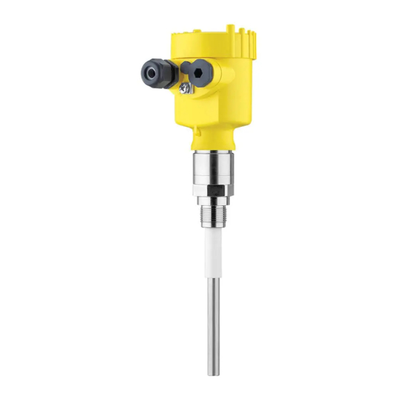
• Only for instrument versions without SIL qualification Constituent parts The VEGACAP 62 consists of the components: • Process fitting with probe • Housing with electronics • Housing lid Fig. 1: VEGACAP 62, rod version with plastic housing Housing lid Housing with electronics 3 Process fitting VEGACAP 62 • Two-wire... - Page 8 Alternatively, you can access the data via your smartphone: • Download the VEGA Tools app from the " Apple App Store" or the " Google Play Store" • Scan the QR-code on the type label of the device or •...
-
Page 9: Principle Of Operation
3 Product description Principle of operation Application area VEGACAP 62 is a point level sensor for use in all areas of industry. The partly insulated probe is suitable for the measurement of bulk solids and liquids. The proven mechanical construction offers high functional safety. Functional principle Probe, measured product and vessel wall form an electrical capacitor. -
Page 10: Packaging, Transport And Storage
Protective cover The protective cover protects the sensor housing against soiling and intense heat from solar radiation. Flanges Screwed flanges are available in different versions according to the following standards: DIN 2501, EN 1092-1, BS 10, ASME B 16.5, JIS B 2210-1984, GOST 12821-80. VEGACAP 62 • Two-wire... -
Page 11: Mounting
Use the recommended cables (see chapter " Connecting to power supply") and tighten the cable gland. You can give your instrument additional protection against moisture penetration by leading the connection cable downward in front of the cable gland. Rain and condensation water can thus drain off. This VEGACAP 62 • Two-wire... - Page 12 Condensation If condensate forms on the vessel top, the run-off liquid can cause bridging and hence faulty switchings. For this reason, use a screening tube or a longer insulation. The length depends on the amount of condensate and the drain-off be- haviour of the product. VEGACAP 62 • Two-wire...
-
Page 13: Mounting Instructions
Agitators and fluidization Due to the effects of agitators, equipment vibration or similar, the level switch can be subjected to strong lateral forces. For this reason, do not use an overly long electrode for VEGACAP 62, but check if you can mount a short level switch on the side of the vessel in horizontal position. Extreme vibration caused by the system, e.g. due to agitators or turbulence in the vessel from fluidisation, can cause the probe of VEGACAP 62 to vibrate in resonance. - Page 14 To achieve a very precise switching point, you can install VEGACAP 62 horizontally. However, if the switching point can have a tolerance of a few centimeters, we recommend mounting VEGACAP 62 approx. 20° inclined to the vessel bottom to avoid buildup. Install rod probes in such a way that the probe projects freely into the vessel. When the instrument is mounted in a tube or nozzle, buildup...
- Page 15 The probe must be mounted in a way that takes the arrangement of the filling and emptying apertures into account. To compensate measurement errors caused by the material cone in cylindrical vessels, the sensor must be mounted at a distance of d/6 from the vessel wall. Fig. 7: Filling and emptying centred VEGACAP 62 • Two-wire...
- Page 16 4 Mounting Fig. 8: Filling in the centre, emptying laterally VEGACAP 62 Discharge opening Filling opening VEGACAP 62 • Two-wire...
-
Page 17: Connecting To Power Supply
Connect the operating voltage according to the following diagrams. Take note of the general installation regulations. As a rule, connect VEGACAP 62 to vessel ground (PA), or in case of plastic vessels, to the next ground potential. On the side of the instrument housing there is a ground terminal between the cable entries. -
Page 18: Wiring Plan - Single Chamber Housing
Wiring plan - single chamber housing Housing overview Fig. 10: Material versions - single chamber housing Plastic (not with dust-Ex) Aluminium Stainless steel Filter element for pressure compensation or blind plug with version IP66/ IP68, 1 bar VEGACAP 62 • Two-wire... - Page 19 " Ex-technical data" are available in the " Safety information". The wiring example is applicable for all suitable controllers. Take note of the operating instructions manual of the controller. Suit- able controllers are listed in chapter " Technical data". Fig. 12: Wiring plan Voltage supply VEGACAP 62 • Two-wire...
-
Page 20: Wiring Plan - Version Ip66/Ip68, 1 Bar
After connecting to voltage supply or after a voltage recurrence, the instrument passes a certain switch on routine. By lowering the current value when switching on, the instrument can output briefly a fault signal. I/mA 20,5 < 2,3 Fig. 14: Warm-up reaction Measured value VEGACAP 62 • Two-wire... -
Page 21: Setup
Note: As a rule, always set the mode with the mode switch of the signal conditioning instrument before starting setup VEGACAP 62. The switching output will change if you set the mode switch afterwards. This could possibly trigger other connected instruments or devices. - Page 22 Measuring range selec- tion switch (1) selection switch (1) on VEGACAP 62 you can change the sensitivity of the probe to the electrical properties of the product and the condi- tions in the vessel. This is necessary so that the level switch can also reliably detect products e.g. with very low or very high dielectric figure.
-
Page 23: Diagnostics And Servicing
Should these measures not be successful, please call in urgent cases 24 hour service hotline the VEGA service hotline under the phone no. +49 1805 858550. The hotline is also available outside normal working hours, seven days a week around the clock. -
Page 24: Exchange Of The Electronics Module
Fig. 17: Check the resistance in the probe Shielding Measuring probe Ground potential Exchange of the electronics module In general, all oscillators of series CP60 can be interchanged. VEGACAP 62 • Two-wire... - Page 25 10. Screw in and tighten the two holding screws with a screwdriver (Torx size T10 or Phillips 4) 11. Insert the wire ends into the open terminals according to the wir- ing plan 12. Press down the opening levers of the terminals, you will hear the terminal spring closing VEGACAP 62 • Two-wire...
-
Page 26: Shortening Of The Probe
Fig. 20: Compensation key Measuring range selection switch (compensation key) Control lamp 3. Keep the measuring range selection switch (1) pushed until the control lamp (2) flashes green. 4. Hence the probe is compensated to the modified length. 5. Carry out the adjustment again. See chapter " Set-up, adjustment elements". VEGACAP 62 • Two-wire... -
Page 27: How To Proceed If A Repair Is Necessary
Clean the instrument and pack it damage-proof • Attach the completed form and, if need be, also a safety data sheet outside on the packaging • Ask the agency serving you to get the address for the return ship- ment. You can find the agency on our homepage. VEGACAP 62 • Two-wire... -
Page 28: Dismount
If personal data is stored on the old device to be disposed of, delete it before disposal. If you have no way to dispose of the old instrument properly, please contact us concerning return and disposal. VEGACAP 62 • Two-wire... -
Page 29: Supplement
0.8 … 4 kg (0.18 … 8.82 lbs) process fitting) Ʋ Rod weight: ø 12 mm (0.472 in) 900 g/m (9.9 oz/ft) Sensor length (L) 0.1 … 6 m (0.328 … 19.69 ft) Max. lateral load 10 Nm (7.4 lbf ft) VEGACAP 62 • Two-wire... - Page 30 0 … +1 bar/0 … 100 kPa (0 … 14.5 psig) Process temperature VEGACAP 62 of -50 … +150 °C (-58 … +302 °F) 316L Process temperature VEGACAP 62 of St -20 … +150 °C (-4 … +302 °F) C22.8 Process temperature (thread or flange -50 …...
- Page 31 1000 m (3280 ft) Ʋ Min. bending radius 25 mm (0.984 in) with 25 °C (77 °F) Ʋ Diameter approx. 8 mm (0.315 in) Ʋ Colour - standard PE Black Ʋ Colour - standard PUR Blue VEGACAP 62 • Two-wire...
-
Page 32: Dimensions
They are part of the delivery or can be downloaded by entering the serial number of your instrument into the search field under www.vega.com as well as in the general download area. Dimensions The following dimensional drawings represent only an extract of all possible versions. Detailed dimensional drawings can be downloaded at www.vega.com/downloads under " Drawings". VEGACAP 62 • Two-wire... - Page 33 ~ 103 mm (5.91") (4.06") ø 77 mm ø 84 mm (3.03") (3.31") M20x1,5 M20x1,5 M20x1,5 Fig. 23: Housing versions with protection rating IP66/IP68 (1 bar) Stainless steel single chamber (precision casting) Aluminium - single chamber VEGACAP 62 • Two-wire...
- Page 34 G ¾, G 1, G 1½ ø 16 mm (0.63") 12 mm (0.47") Fig. 24: VEGACAP 62, threaded version G1 (ISO 228 T1) Sensor length, see chapter " Technical data" ø 40 mm (1.58") Fig. 25: Temperature adapter VEGACAP 62 • Two-wire...
- Page 35 Length of the screening tube, see chapter " Technical data" ø 27 mm (1.06") Fig. 27: VEGACAP 62, concentric tube, for example with small dielectric constant or for linearization Concentric tube length, see chapter " Technical data" VEGACAP 62 • Two-wire...
-
Page 36: Industrial Property Rights
Les lignes de produits VEGA sont globalement protégées par des droits de propriété intellec- tuelle. Pour plus d'informations, on pourra se référer au site www.vega.com. VEGA lineas de productos están protegidas por los derechos en el campo de la propiedad indus- trial. Para mayor información revise la pagina web www.vega.com. - Page 37 Notes VEGACAP 62 • Two-wire...
- Page 38 Notes VEGACAP 62 • Two-wire...
- Page 39 Notes VEGACAP 62 • Two-wire...
- Page 40 Subject to change without prior notice © VEGA Grieshaber KG, Schiltach/Germany 2023 VEGA Grieshaber KG Am Hohenstein 113 Phone +49 7836 50-0 77761 Schiltach E-mail: info.de@vega.com...
Need help?
Do you have a question about the VEGACAP 62 and is the answer not in the manual?
Questions and answers