
Subscribe to Our Youtube Channel
Related Manuals for Force USA F-ULPHS


Summary of Contents for Force USA F-ULPHS
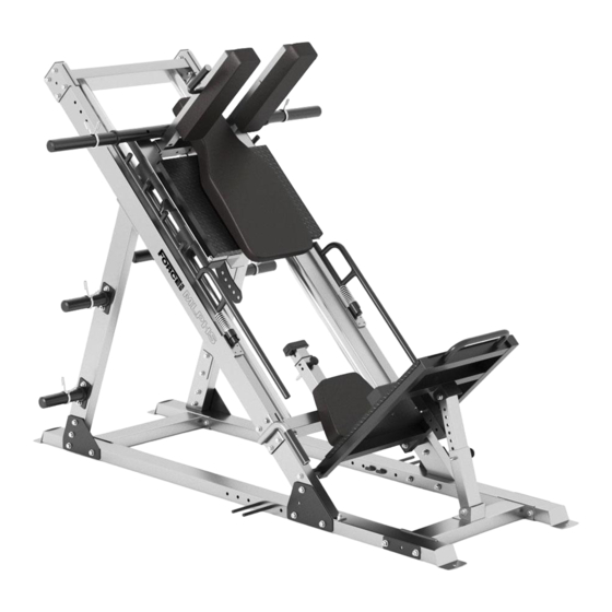
- Page 1 OWNER’S MANUAL F-ULPHS Force USA Ultimate 45⁰ Leg Press/ Hack Squat Combo CAUTION! Read all precautions and instructions in this manual before using this equipment.
-
Page 2: Assembly Manual
OVER THE AGE OF 35 OR HAVE PRE-EXISTING HEALTH PROBLEMS. READ ALL INSTRUCTIONS BEFORE ASSEMBLING OR USING ANY FITNESS EQUIPMENT. FORCE USA FITNESS EQUIPMENT ASSUMES NO RESPONSIBILITY FOR PERSONAL INJURY OR PROPERTY DAMAGE SUSTAINED BY OR THROUGH THE USE OF THIS PRODUCT. -
Page 3: Parts List
PARTS LIST NOTE: SOME PARTS MAY COME PRE ASSEMBLED, IN WHICH CASE CONTINUE ONTO THE NEXT REQUIRED STEP OF ASSEMBLY KEY NO. PART DESCRIPTION F-ULPHS SPEC Left Stabilizer Right Stabilizer Front Connecting Frame Rear Connecting Frame Support Frame Frame Lower Crossmember... - Page 4 □70×50 End Cap □60×□50 Sliding Sleeve Bumper 100×50×25 Φ16 Lock Pin Φ43×φ27×Φ8×80 Spring Φ23×150 Grip Hexagon Socket Button Head Screws M8×25 Allen Screw M8×8 Allen Bolt M8×16 Allen Bolt M8×25 Allen Bolt M10×25 Hex Bolt M12×25 Hex Bolt M12×110 Hex Bolt M10×125 Hex Bolt M10×120...
-
Page 5: Exploded Diagram
EXPLODED DIAGRAM... -
Page 6: Assembly Diagram
ASSEMBLY DIAGRAM 1 USE A PARTNER TO HELP WITH THIS STEP REMEMBER: Only hand tighten all nuts and bolts until whole F-ULPHS is assembled. 1. Ensuring correct orientation, attach the Front Connecting Frame (Key #3) to the Left Stabilizer (Key #1) and Right Stabilizer (Key #2) using 240×158×5 Bracket (Key #29), M10×125 Hex Bolt (Key #57), Washer 10 (Key #71), and M10 Aircraft Nut (Key #69). - Page 7 ASSEMBLY DIAGRAM 2 USE A PARTNER TO HELP WITH THIS STEP REMEMBER: Only hand tighten all nuts and bolts until whole F-ULPHS is assembled. 1. Ensuring correct orientation, connect the Support Frame (Key #5) over the sockets on top of the Left Stabilizer (Key #1) and Right Stabilizer (Key #2) using M10×70 Hex Bolt (Key #60) with...
- Page 8 ASSEMBLY DIAGRAM 3 USE A PARTNER TO HELP WITH THIS STEP REMEMBER: Only hand tighten all nuts and bolts until whole F-ULPHS is assembled. 1. Attach the Upper Crossmember (Key #8) into the top of the Frames (Key #6) and connect using 120×101×4 Bracket (Key #31), M10×70 Hex Bolt (Key #60), Washer 10 (Key #71), and M10...
- Page 9 ASSEMBLY DIAGRAM 4 USE A PARTNER TO HELP WITH THIS STEP REMEMBER: Only hand tighten all nuts and bolts until whole F-ULPHS is assembled. 1. Attach Safety Support (Key #28) to the Lower Crossmember (Key #7) and lock with Lock Pin (Key #47).
- Page 10 ASSEMBLY DIAGRAM 5 USE A PARTNER TO HELP WITH THIS STEP REMEMBER: Only hand tighten all nuts and bolts until whole F-ULPHS is assembled. 1. Sliding Frame Assembly: Position Rollers (Key #37) on top and below of the Guide Rods (Key #9) and slide inside the Sliding Frame (Key #10) brackets, then secure with M12×110 Hex Bolt...
- Page 11 ASSEMBLY DIAGRAM 6 USE A PARTNER TO HELP WITH THIS STEP REMEMBER: Only hand tighten all nuts and bolts until whole F-ULPHS is assembled. 1. Attach the Lower Weight Carriage (Key #17) beneath the Sliding Frame (Key #10) and slot the Shoulder Pad Mount (Key #13) above the Sliding Frame (Key #10), then connect both using 120×50×3 Bracket (Key #30), M10×70 Hex Bolt (Key #60), Washer 10 (Key #71), and M10...
- Page 12 ASSEMBLY DIAGRAM 7 USE A PARTNER TO HELP WITH THIS STEP REMEMBER: Only hand tighten all nuts and bolts until whole F-ULPHS is assembled. 1. Ensuring correct orientation, connect the Lower Adjuster (Key #12) to the Left Stabilizer (Key #1) and Right Stabilizer (Key #2) using M10×20 Hex Bolt (Key #63), Washer 10 (Key #71), and Axle (Key #27).
- Page 13 USE A PARTNER TO HELP WITH THIS STEP REMEMBER: Only hand tighten all nuts and bolts until whole F-ULPHS is assembled. 1. Attach the Weights Stow Brackets (Key #21) on both sides of the Support Frame (Key #5) and secure with 120×70×3 Bracket (Key #32), M10×70 Hex Bolt (Key #60), Washer 10 (Key #71), and M10 Aircraft...
- Page 14 BOLTS, NUTS, WASHERS and SCREWS...
- Page 17 PARTS LIST BOX 1: BOX 3: Part 1 Part 12 1 Part 2 Part 10 2 Part 9 Part 18 1 Part 19 Part 34 BOX 2: Part 36 BOX 4: 2 Part 5 2 Part 14 Part 11 4 Part 20 Part 3 1 Part 24 Part 25...
- Page 18 Offering one of the best warranties on the market for your peace of mind, each piece of Force USA strength equipment is hand crafted for quality and we use state-of-the-art production methods for our entire range. The Force USA range of strength equipment carries a Lifetime Structural Warranty along with 2 years cover on all cables and pulleys.
Need help?
Do you have a question about the F-ULPHS and is the answer not in the manual?
Questions and answers