
Related Manuals for Force USA F-GHR


Summary of Contents for Force USA F-GHR
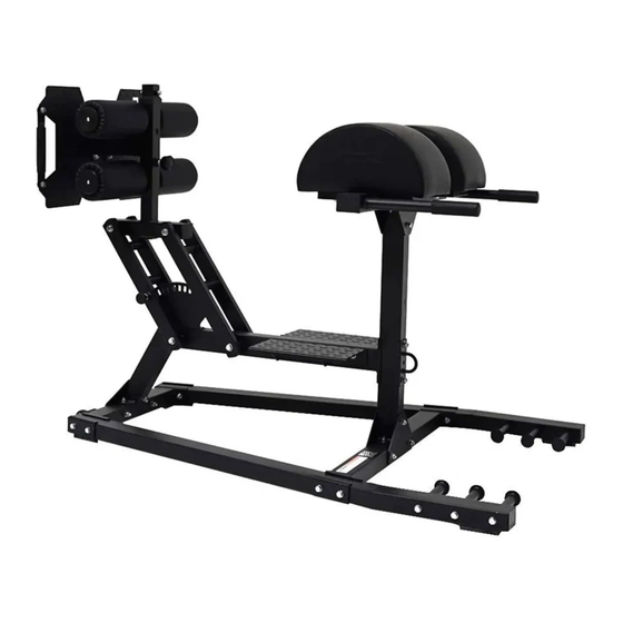
- Page 1 F-GHR OWNER’S MANUAL Glute Ham Raise CAUTION! Read all precautions and instructions in this manual before using this equipment.
-
Page 2: Before You Start
THE AGE OF 35 OR HAVE PRE-EXISTING HEALTH PROBLEMS. READ ALL INSTRUCTIONS BEFORE ASSEMBLING OR USING ANY FITNESS EQUIPMENT. FORCE USA FITNESS EQUIPMENT ASSUMES NO RESPONSIBILITY FOR PERSONAL INJURY OR PROPERTY DAMAGE SUSTAINED BY OR THROUGH THE USE OF THIS PRODUCT. - Page 3 KEY NO. DESCRIPTION SPEC Q'TY Main Base Frame Front Stabilizer Rear Stabilizer Front Support Rear Support Cross Brace Left Sliding Block Right Sliding Block Left Guide Rod Right Guide Rod Adjustable Frame Foam Adjustment Bracket Pad Support Frame Foot Frame Weight Post Foot Plate Foam Baffle...
-
Page 4: Assembly Diagram
3. Ensuring the MAIN BASE FRAME (1) is correctly orientated, with the side bolt holes towards the front of the F-GHR, align the rear end of the MAIN BASE FRAME (1) with the base of the REAR SUPPORT (5) Attach... - Page 5 USE A PARTNER TO HELP WITH THIS STEP REMEMBER: Only hand tighten all nuts and bolts until whole F-GHR is assembled 1. Slot the LEFT GUIDE ROD (9) over the left socket on the top of the REAR SUPPORT (5) Attach using a HEX BOLT M10X60 (36), two WASHER 10 (44) and an AIRCRAFT NUT M10 (46) 2.
- Page 6 ASSEMBLY DIAGRAM 3 REMEMBER: Only hand tighten all nuts and bolts until whole F-GHR is assembled Attach the two END CAP45 (24) to the ends of the cross bars on the FRONT SUPPORT (4) Skip this step if already pre-assembled) 2.
- Page 7 USE A PARTNER TO HELP WITH THIS STEP REMEMBER: Only hand tighten all nuts and bolts until whole F-GHR is assembled Attach the four END CAP 25X50 (22) to the ends of the cross bars on the CROSS BRACE (6)
- Page 8 ASSEMBLY DIAGRAM 5 REMEMBER: Only hand tighten all nuts and bolts until whole F-GHR is assembled Attach the four END CAP32 (32) to the ends of the bars on the back of the FOOT FRAME (14) Skip this step if already pre-assembled) 2.
- Page 9 ASSEMBLY DIAGRAM 6 REMEMBER: Only hand tighten all nuts and bolts until whole F-GHR is assembled Position the two FOOT PLATES (16) over the bolt holes on the CROSS BRACE (6) Attach from above using four SUNK SCREWS M8X65 (37) four WASHER8 (45) and four AIRCRAFT NUT M8 (43)
- Page 10 ASSEMBLY DIAGRAM 7 REMEMBER: Only hand tighten all nuts and bolts until whole F-GHR is assembled Attach the four END CAP25 (26) into the ends of the two WEIGHT POSTS (15) Skip this step if already pre- assembled) 2. Slide the two WEIGHT POSTS (15) into a hole on each side of the FRONT STABILIZER (2) and attach a SPRING CLIP (20) to each post.
-
Page 11: Exploded Diagram
EXPLODED DIAGRAM... - Page 13 /852...
-
Page 14: Warranty
Offering one of the best warranties on the market for your peace of mind, each piece of Force USA strength equipment is hand crafted for quality and we use state-of-the-art production methods for our entire range. - Page 15 F-GHR Box one 1×part 14 1x part 6 2×part 16 1×part 9 1×part 10 1×part 7 1x part 8 1×part 1 1×part 2 1×part 11 1×part 3 2x part 12 2×part 15 1×part 5 1×part 4 3×part 23 1x part 18 1×part 19...
Need help?
Do you have a question about the F-GHR and is the answer not in the manual?
Questions and answers