
Related Manuals for Force USA F-G6


Summary of Contents for Force USA F-G6
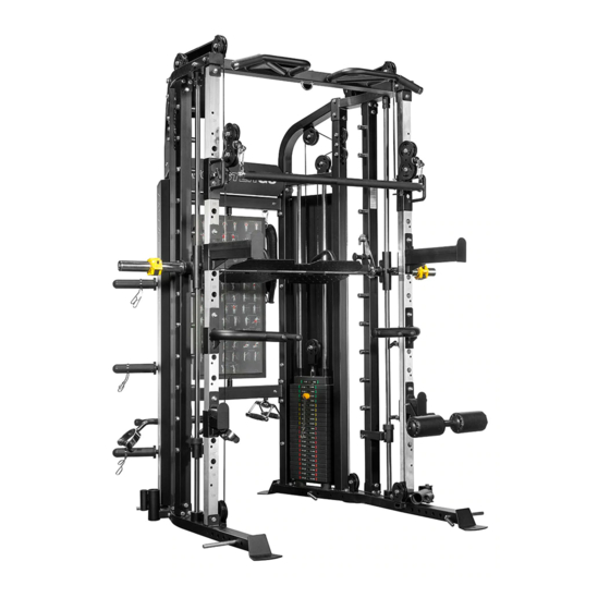
- Page 1 F-G6 OWNER’S MANUAL CAUTION! Read all precautions and instructions in this manual before using this equipment.
-
Page 2: Assembly Manual
OF 35 OR HAVE PRE-EXISTING HEALTH PROBLEMS. READ ALL INSTRUCTIONS BEFORE ASSEMBLING OR USING ANY FITNESS EQUIPMENT. FORCE USA FITNESS EQUIPMENT ASSUMES NO RESPONSIBILITY FOR PERSONAL INJURY OR PROPERTY DAMAGE SUSTAINED BY OR THROUGH THE USE OF THIS PRODUCT. SAVE THESE INSTRUCTIONS. -
Page 3: Table Of Contents
Parts list Key No. Quantity Description of part right stabilizer right rear vertical frame left upper frame short connection frame right center vertical frame right front vertical frame Right moving frame cross beam L shape bracket upper connection frame weight plate holder pulley bracket barbell holder left chin up bar... - Page 4 bracket Push bar Weight plate cover bottom bracket Weight plate cover upper bracket left rear vertical frame weight stack inner bracket weight stack cover Left stabilizer light upper frame left center vertical frame right chin up bar pulley bracket Right safety bar Left bearing house bracket left front vertical frame...
- Page 5 weight plate Plastic guide Weight stem Bearing bearing □75×□60 sleeve pulley pulley 7# Carabiner Adjustable single strap L=8270 cable Bushing Bearing V shape handle ankle strap Shiver bar triceps rope Rubber bumper M12×75 Hex bolt φ12 washer M12 Aircraft nut M12×95 Hex bolt M12×100 Hex bolt φ10 washer...
- Page 6 Big washer M12×85 Hex bolt M10×100 Allen bolt M10×95 Allen bolt M10 Aircraft nut M10×50 Allen bolt M10×85 Allen bolt M10×70 Allen bolt M10×60 Allen bolt M6×43 Allen bolt φ25×2 End cap M10*25 Sunk bolt M12×90 Hex bolt φ10×80 pin φ40 bead flange φ26 bead flange φ19×1.5 End cap...
-
Page 7: Hardware Identifier
HARDWARE IDENTIFIER Note: The following parts are not drawn to scale, Please use your own ruler to measure the size. - Page 11 COMPONENT...
-
Page 15: Right Stabilizer
ASSEMBLY INSTRUCTION Step 1 Attach the right center vertical frame(5#) onto the right stabilizer(1#),Secure them with 1 pc L shape bracket(9#),2pcs M12*75 Hex bolt(73#),2pcs M12*95 Hex bolt(76#) ,8pcs φ12 washer (74#),4pcs M12 Aircraft nut (75#). Attach the right rear vertical frame(2#) onto the right stabilizer(1#), Secure them together with the barbell holder(13#)together, with the same way in A and using 1 pc L shape bracket(9#),2pcs M12*75 Hex bolt(73#),2pcs M12*100 Hex bolt(77#) ,8pcs φ12 washer (74#),4pcs M12 Aircraft nut (75#). - Page 16 Step2 Using the same way in Step 1 to install the left rear vertical frame (31#),left center vertical frame(36#) and 2 pcs guide rods(16#).
-
Page 17: Cross Beam
Step3 Attach the both end of the cross beam (8#)to the right rear vertical frame(2#) and left rear vertical frame (31#) as the diagram shows. Secure one end with Secure them with 1 pc L shape bracket(9#),2pcs M12*75 Hex bolt(73#),2pcs M12*95 Hex bolt(76#) ,8pcs φ12 washer (74#),4pcs M12 Aircraft nut (75#). Assemble another end with the same way in A. - Page 18 Step 4 Attach the 3pcs J-shape hook (15#)as the diagram shows and secure them with 3pcs φ10 washer(78#) and 3 pcs M10 Aircraft nut(87#) separately. Thread the 2 pcs round hook (18#) as the diagram shows.
- Page 19 Step 5 Install the 46 pcs barbell holder (19#) into the holes and secure them with 46 pcs M10*85 Allen bolt(89#) and46 pcs φ10 washer (78#).
-
Page 20: Weight Plate Holder
Step 6 Attach the weight plate holder(11#) into the hole as the diagram shows and secure it with M10*25 Allen bolt(79#) andφ10 washer (78#). Attach the sleeve (103#) and spring collar (104#) as the diagram shows. Repeat the same way to install another . - Page 21 Step 7 Install the next 2 pcs weight plate holder(11#) as the diagram shows again with the same way in Step 6.
- Page 22 Step 8 Attach the left upper frame (3#) onto left center vertical frame(36#) ,Secure them with 2pcs M12*75Hex bolt (73#),4pcs φ12 washer (74#),1 pc bracket (41#) and 2 pcs M12 Aircraft nut (75#). Install the right upper frame(35#) with the same way in A.
- Page 23 Step 9 Install the cross beam(8#) with the same way in STEP 3.
- Page 24 Step 10 Attach the weight stack cover bracket (29#) as the diagram shows , secure it with the triangle bracket(20#) using 2 pcs M10*100 Allen bolt(85#),4pcs φ10 washer (78#) , 1 pc bracket (41#),and 2pcs M10 Aircraft nut(87#). Secure another end with the 1 pc M10*100 Allen bolt(85#),2pcs φ10 washer (78#) , 1 pc M10 Aircraft nut(87#).
- Page 25 Step 11 Use the above way in Step 10 to install another side.
- Page 26 Step 12 Attach the upper connection frame (10#) between the light upper frame (35#) and the left upper frame (3#) ,Secure them with 4 pcs M12*95 Hex bolt (76#),8pcs φ12 washer(74#)and 4pcs M12 Aircraft nut(75#).
-
Page 27: Guide Rod
Step 13 A. Place 2pcs rubber bumper(54#) along the guide rod and then place 19 pcs weight plate (55#) along the guide rod, insert the selector rod (17#) into the hole and place 1 pc weight stem(57#),Secure the weight stem(57#) with the selector rod(17#) with 2pcs M10*25 Sunk bolt (94#). - Page 28 Step 14 Use the same way in step 13 to install another.
- Page 29 Step 15 Attach the short connection frame(4#)as the diagram shows. Attach the LOGO board (50#) together and secure them with 2pcs M10*70 Allen bolt(90#),6pcs φ10 washer(78#),2pcs M10 Aircraft nut(87#).2pcs M10*25 Allen bolt (79#).
- Page 30 STEP 16 Use the same way in step 15.
- Page 31 STEP 17 Secure the guide rod(16#) with the short connection frame(4#) together with 2pcsM10*25 Allen bolt (79#) and 2 pcs φ10 washer (78#). Install another with the same way .
- Page 32 STEP 18 Attach the right front vertical frame(6#) onto the right stabilizer(1#), Secure them with 2pcs M12*85 Hex bolt (84#),4pcs φ12 washer (74#) and 2 pcM12 Aircraft nut (75#). Use the same way to install another one.
- Page 33 STEP 19 Attach the pulley bracket (12#) to the moving frame and secure them together with 1pc M12×90 Allen bolt(95#), 2pcs φ12 washer (74#) and 1 pcM12 Aircraft nut (75#). Use the same way to install another.
- Page 34 STEP 20...
- Page 35 A.Place 2 pcs pulleys onto & below the cable,Secure the pulleys with 2pcs M10 *50 Allen bolt (88#),4pcs φ10 washer (78#) and M10 Aircraft nut (87#). B.Draw the cable around the pulley and upwards,Place 1 pc pulley below the cable and secure the pulley with the same way in A.
-
Page 36: Bearing Frame
STEP 21 Slide the bearing frame(22#), crunch (39#)along the bearing guide rod(21#), Secure the guide rod with 2pcs M10× 25 allen bolt (79#) and 2pcs φ10 washer(78#). Use the same way to install another. -
Page 38: Bearing House
STEP 22 The 4 pcs bearing(59#),2pcs bearing house(23#),2pcs adjustable washer(49#) and 2pcs M10*25 Allen bolts were installed in the factory. -
Page 39: Barbell
STEP 23 Attach the bearing frame (22#) with the barbell together and secure them with 3pcsM10×25 Allen bolt (79#),5pcs φ10 washer(78#) and 2pcs M10 Aircraft nut (87#). -
Page 40: Bracket
STEP 24 Attach the 2 pcs weight stack inner bracket(32#) through the upper & bottom opening of the weight stack cover (33#) and secure the weight stack cover to the bracket with 6pcs M6*15 Allen bolt (81#) and 6 pcsφ6 washer (80#) and 6pcs M6 Aircraft nut(82#). -
Page 41: Right Chin Up Bar
STEP 25 Attach the left & right chin up bar(14#&37#) to the upper connection frame(10#), secure them with 4pcs M10*25 Allen bolt(79#) and 4pcs φ10 washer(78#). - Page 42 STEP 26 Attach the big hook (51#) through the hole and secure it with 2pcs φ12 washer (74#) and 2pcs M12 aircraft nut (75#) .
- Page 43 STEP 27 Attach the shiver bar (70#), triceps rope (71#),V shape handle(68#),ankle strap(69#) to the hooks separately as the diagram shows.
-
Page 44: Right Safety Bar
STEP 28 A. Attach the left& right safety bar(44#&45#) into the holes as the diagram shows. B. Attach the left& right crunch (46#&47#) into the holes as the diagram shows. C. Attach the 4pcs pin (26#) into the holes of the stabilizer. -
Page 45: Pulley
Offering one of the best warranties on the market for your peace of mind, each piece of Force USA strength equipment is hand crafted for quality and we use state-of-the-art production methods for our entire range.
Need help?
Do you have a question about the F-G6 and is the answer not in the manual?
Questions and answers