
Related Manuals for Force USA F-CLP


Summary of Contents for Force USA F-CLP
- Page 1 OWNER’S MANUAL F-CLP Force USA Compact LEG Press/Calf Raise CAUTION! Read all precautions and instructions in this manual before using this equipment.
-
Page 2: Assembly Manual
ARE OVER THE AGE OF 35 OR HAVE PRE-EXISTING HEALTH PROBLEMS. READ ALL INSTRUCTIONS BEFORE ASSEMBLING OR USING ANY FITNESS EQUIPMENT. FORCE USA FITNESS EQUIPMENT ASSUMES NO RESPONSIBILITY FOR PERSONAL INJURY OR PROPERTY DAMAGE SUSTAINED BY OR THROUGH THE USE OF THIS PRODUCT. - Page 3 PARTS LIST F-UPC KEY NO. PART DESCRIPTION F-CLP SPEC Q'ty KEY NO. PART DESCRIPTION F-CLP SPEC Q'ty Front Stabilizer Square End Cap 6 0×30 □ Rear Stabilizer Square End Cap 8 0×40 □ Connecting Frame Bracket Rear Connecting Frame Square End Cap φ25...
- Page 9 1. Attach Connecting Frame (3), Rear Stabilizer (2) and Rear Connecting Frame (4) using M10x75 Bolts (58) vertically and M10x95 Bolts (54) horizontally with Washers (62) and Nuts (59) 2. Attach Connecting Frame (3), Front Stabilizer (1) and Skew Frame (8) using M10x75 Bolts (58) vertically and M10x95 Bolts (54) horizontally with Washers (62) and Nuts (59) 3.
- Page 10 Attach the 2 x Inclined Support Frames (18) to Rear Stabilizer (2) and Rear Connecting Frame (4) using M10x70 Bolts (51), M10x85 Bolts (53), Washers (62) and Nuts (59)
- Page 11 1. Attach the 2 x Guide Rods (13) to the Skew Frame (8) with M12x25 Bolts (56), Spring Washers (64) and Washers (63) 2. Position the Pin Axle (20) on the Skew Frame (8) and slide the Sliding Frame (10) onto the Guide Rods so that it rests against the Pin Axle 3.
- Page 12 1. Attach Adjuster (5) to Sliding Frame (10) with M10x80 Bolt (52), Washers (62) and M10 Nut (59) 2. Slide the Backrest Pad Adjuster (6) into the Adjuster (5) and add the Magnetic Pin (25) 3. Attach the Backrest Pad Mount (7) to the Backrest Pad Adjuster (6) with M10x110 Bolt (55), Washers (62) and M10 Nut (59) 4.
- Page 13 1. Attach the Adjuster (9) to the Foot Stand (11) with M10x80 Bolt (52), Washers (62) and M10 Nut (59) 2. Attach the Adjuster (5) to the Skew Frame (8) with M10x80 Bolt (52), Washers (62) and M10 Nut (59) 3.
- Page 14 1. Slide the Bearing Rod (22) through the Sliding Frame (10) so that it is exposed on either side 2. Attach the Right Hand Stand (16) to the Sliding Frame (10) with M10x25 Bolt (65), Washers (62) and M10 Nut (59) 3.
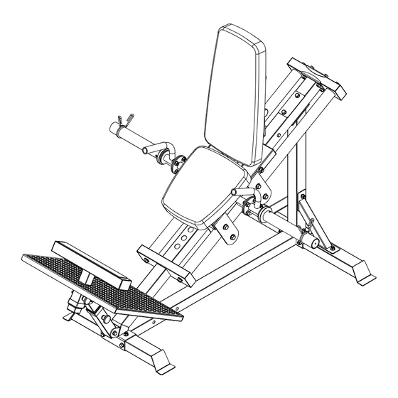
- Page 15 1. Attach the Seat Pad (23) to the Sliding Frame (10) with M8x60 Bolts (50) and 8mm Washers (61) 2. Attach the Backrest Pad (24) to the Backrest Pad Mount (7) with M8x20 Bolts (49) and 8mm Washers (61) 3. Now that hand assembly is completed, ensure everything is tightened using the necessary tools such as Wrench and Allen Key...
- Page 17 BOX 1: Part 2 Part 3 Part 4 Part 5 Part 6 Part 8 Part 13 Part 18 Part 21 Part 22 Part 23 Part 24 Part 29 Part 31 Part 38 F-UPC Assembly Manual Parts bag 3-1 Parts bag 3-2 Parts bag 3-3 BOX 2: Part 1...
- Page 18 Offering one of the best warranties on the market for your peace of mind, each piece of Force USA strength equipment is hand crafted for quality and we use state-of-the-art production methods for our entire range.
Need help?
Do you have a question about the F-CLP and is the answer not in the manual?
Questions and answers