
Related Manuals for Force USA F-HPR


Summary of Contents for Force USA F-HPR
- Page 1 F-HPR OWNER’S MANUAL HOME POWER RACK CAUTION! Read all precautions and instructions in this manual before using this equipment.
- Page 2 THE AGE OF 35 OR HAVE PRE-EXISTING HEALTH PROBLEMS. READ ALL INSTRUCTIONS BEFORE ASSEMBLING OR USING ANY FITNESS EQUIPMENT. FORCE USA FITNESS EQUIPMENT ASSUMES NO RESPONSIBILITY FOR PERSONAL INJURY OR PROPERTY DAMAGE SUSTAINED BY OR THROUGH THE USE OF THIS PRODUCT.
- Page 3 KEY NO. DESCRIPTION SPEC Left Vertical Beam Right Vertical Beam Rear Left Vertical Frame Rear Right Vertical Frame Main Base Frame Upper Side Frame Rear Top Beam Rear Base Frame Base Frame Weight Glide Post Rear Upper Frame eft Arm Support Arm Support Right eft Bar Holder...
- Page 4 ASSEMBLY DIAGRAM 1 USE A PARTNER TO HELP IN THIS STEP REMEMBER: Only hand tighten all nuts and bolts until whole F-HPR is assembled Skip this step if already pre- 1. Attach the four BASE FRAME END CAPS (37) to the ends of both MAIN BASE FRAMES (5) ( assembled) 2.
- Page 5 ASSEMBLY DIAGRAM 2 USE A PARTNER TO HELP IN THIS STEP REMEMBER: Only hand tighten all nuts and bolts until whole F-HPR is assembled Attach the REAR BASE FRAME (8) to the bottom socket of the REAR LEFT VERTICAL FRAME (3)
- Page 6 USE A PARTNER TO HELP IN THIS STEP REMEMBER: Only hand tighten all nuts and bolts until whole F-HPR is assembled 1. Attach a MAIN BASE FRAME (5) to the REAR RIGHT VERTICAL FRAME (4) using two HEX BOLT M10X65 (41), four WASHER10 (49) and two AIRCRAFT NUT M10 (48) 2.
- Page 7 ASSEMBLY DIAGRAM 4 REMEMBER: Only hand tighten all nuts and bolts until whole F-HPR is assembled 1. Attach THE BASE FRAME (9) to the REAR BASE FRAME (8) using a BRACKET 110X45X3 (23), two HEX BOLT M10X65 (41), four WASHER10 (49) and two AIRCRAFT NUT M10 (48) 2.
- Page 8 ASSEMBLY DIAGRAM 5 REMEMBER: Only hand tighten all nuts and bolts until whole F-HPR is assembled 1. Position the stoppered end of the CABLE (26) at the front end of the REAR UPPER FRAME (11) and draw the cable up into the bracket.
- Page 9 ASSEMBLY DIAGRAM 6 REMEMBER: Only hand tighten all nuts and bolts until whole F-HPR is assembled 1. Position the stoppered end of a CABLE (26) at the front of the BASE FRAME (9) and draw the cable through the circular bracket.
- Page 10 SIDE-VIEW...
- Page 11 ASSEMBLY DIAGRAM 7 REMEMBER: Only hand tighten all nuts and bolts until whole F-HPR is assembled 1. Attach an END CAP (32) to the open end of the LEFT BAR HOLDER (14) and the RIGHT BAR HOLDER (15) 2. Insert the LEFT BAR HOLDER (14) and the RIGHT BAR HOLDER (15) into the weight holes about half way up the front of the front VERTICAL BEAMS (1+2) and through to the holes on the REAR VERTICAL FRAMES (4+5) 3.
- Page 12 ADDITIONAL ASSEMBLY 1. Attach a SQUARE END CAP 45 (33) to the front end of the REAR UPPER FRAME (11) and the top of the WEIGHT GLIDE POST (10) 2. Attach a SQUARE END CAP 38 (34) using a WASHER (40) to the top of the stopper at the base of the WEIGHT GLIDE POST (10) 3.
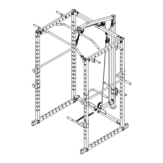
- Page 13 OVERALL EXPLODED VIEW...
- Page 16 Offering one of the best warranties on the market for your peace of mind, each piece of Force USA strength equipment is hand crafted for quality and we use state-of-the-art production methods for our entire range.
- Page 17 F-HPR Box one 1×part 7 1x part 1 1×part 2 1×part 10 1×part 8 2×part 26 1x part 4 4×part 18 2×part 23 2×part 24 2×part 25 6x part 31 1x part 3 Parts bag 1of 2 Parts bag 2of 2 Box two 2×part 6...
Need help?
Do you have a question about the F-HPR and is the answer not in the manual?
Questions and answers