Table of Contents
Advertisement
Quick Links
Sea Tel, Inc.
4030 Nelson Avenue
Concord, CA 94520
Tel: (925) 798-7979
Fax: (925) 798-7986
Web:
http://www.cobham.com/seatel
Sea Tel Inc is also doing business as Cobham SATCOM - Maritime
April 8, 2014
INSTALLATION AND OPERATION MANUAL
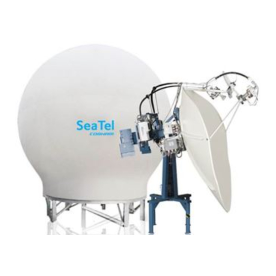
9711-92 KU-BAND TX/RX ANTENNA
WARNING: RF RADIATION HAZARD
This stabilized antenna system is designed to be used with transmit/receive equipment
manufactured by others. Refer to the documentation supplied by the manufacturer which
will describe potential hazards, including exposure to RF radiation, associated with the
improper use of the transmit/receive equipment. Note that the transmit/receive
equipment will operate independently of the stabilized antenna system. Prior to work on
the stabilized antenna system, the power to the transmit/receive system must be locked
out and tagged.
When the transmit/receive system is in operation, no one should be allowed anywhere
within the radiated beam being emitted from the reflector.
The ultimate responsibility for safety rests with the facility operator and the
individuals who work on the system.
FOR SEA TEL MODEL
Sea Tel Europe
Unit 1, Orion Industrial Centre
Wide Lane, Swaythling
Southampton, UK S0 18 2HJ
Tel: 44 (0)23 80 671155
Fax: 44 (0)23 80 671166
Web:
Document. No. 139192 Revision A2
http://www.cobham.com/seatel
Advertisement
Table of Contents
Troubleshooting

Subscribe to Our Youtube Channel
Related Manuals for Sea Tel 9711-92


Summary of Contents for Sea Tel 9711-92
- Page 1 Southampton, UK S0 18 2HJ Fax: (925) 798-7986 Tel: 44 (0)23 80 671155 Web: http://www.cobham.com/seatel Fax: 44 (0)23 80 671166 Web: http://www.cobham.com/seatel Sea Tel Inc is also doing business as Cobham SATCOM - Maritime April 8, 2014 Document. No. 139192 Revision A2...
- Page 2 Copyright © 2013 Sea Tel Inc All Rights Reserved. The information contained in this document is proprietary to Sea Tel, Inc.. This document may not be reproduced or distributed in any form without prior written consent of Sea Tel, Inc. The information in this document is subject to change without notice.
- Page 4 2009 version of FCC 47 C.F.R. § 25.222. Sea Tel hereby declares that the antennas listed below will meet the off-axis EIRP spectral density requirements of § 25.222 (a)(1)(i) with an N value of 1, when the following Input Power spectral density limitations are met: *0.6 Meter Ku Band, Models 2406 and USAT-24 are limited to...
-
Page 5: Table Of Contents
Table of Contents 1. INTRODUCTION ......................................1-1 1.1.................................. 1-1 ENERAL YSTEM ESCRIPTION 1.2........................................... 1-1 URPOSE 1.3................................... 1-1 THER NPUTS TO THE YSTEM 1.4....................................1-1 YSTEM OMPONENTS 1.5................................1-2 NTENNA ONFIGURATION 1.6..................................1-3 NTENNA RBITRATOR 1.7. - Page 6 Table of Contents 3.5............................3-27 NSTALLING THE ELOW ECKS QUIPMENT 3.5.1. General Cautions & Warnings ............................3-27 3.5.2. Preparing BDE Location ..............................3-27 3.5.3. System Configuration ................................3-27 3.5.4. Installing the Below Deck Equipment ......................... 3-28 3.6............................3-28 ONNECTING THE ELOW ECKS...
- Page 7 Table of Contents 7.4..........................................7-1 7.4.1. VSAT Application ..................................7-1 7.5..........................................7-2 7.5.1. VSAT Application ..................................7-2 7.6. SAT SKEW ........................................7-2 7.7. NID ..........................................7-2 8. SETUP – HOME FLAG OFFSET ................................8-1 8.1. ) ..............8-1 LECTRONIC ALIBRATION OF ELATIVE...
- Page 8 Table of Contents 12.8.1. Blockage Simulation Test - SW2 Trigger State: Logic Level LOW ..............12-5 12.8.2. Blockage Simulation Test - SW2 Trigger State: Logic Level HIGH .............. 12-6 12.9. T - DAC-2202 ......................12-6 ESTING THE ATELLITE ODEM NPUT 12.10.
- Page 9 ............................... 20-3 NSTALLING OFTWARE VIA LUETOOTH 20.8. N ..................................20-4 ORMAL PERATION 21. 9711-92 TECHNICAL SPECIFICATIONS ..........................21-1 21.1. 9711-92 S ..................................21-1 PECIFICATIONS 21.2. C ........................................... 21-8 ABLES 21.2.1. Antenna Control Cable (Provided from ACU-MUX) ....................21-8 21.2.2. Antenna Transmit & Receive IF Coax Cables (Customer Furnished) ............21-8 21.2.3.
- Page 10 Table of Contents 22.2. 9711 G ..................................22-1 ENERAL RAWINGS This Page Intentionally Left Blank...
-
Page 11: Introduction
9711-92 Ku-Band TXRX Introduction Introduction WARNING: RF Radiation Hazard - This stabilized antenna system is designed to be used with transmit/receive equipment manufactured by others. Refer to the documentation supplied by the manufacturer which will describe potential hazards, including exposure to RF radiation, associated with the improper use of the transmit/receive equipment. -
Page 12: Dual Antenna Configuration
Introduction 9711-92 Ku-Band TXRX Figure 1 -1 Series 11 TXRX Simplified Block Diagram 1.5. Dual Antenna Configuration Sometimes, due to very large blockage conditions, you may need to install a dual antenna configuration to provide uninterrupted services. Two full antenna systems are installed and the ACU control outputs are connected to an arbitrator switch panel which then is connected to the below decks equipment. -
Page 13: Dual Antenna Arbitrator
9711-92 Ku-Band TXRX Introduction 1.6. Dual Antenna Arbitrator The Dual Antenna Arbitrator panel can pass LNB voltages (and handle 250-400 ma of current) and the RXIF signals on the RX connections. TXIF, Reference and BUC supply voltage can pass through this arbitrator panel to the antenna, but it is not recommended that BUC power be supplied through the dual channel rotary joint of the antenna (a BUC power supply is provided on all Series 09 antenna pedestals). -
Page 14: Interface Requirements
Introduction 9711-92 Ku-Band TXRX 1.7.2. Interface requirements: 1.7.2.1. Hardware Sea Tel Antenna Control Units Model DAC-2202 or DAC-2302. Any Satellite modem manufacturer that is compatible with OpenAMIP CAT5 Patch cable 1.7.2.2. Software Sea Tel model DAC-2202: ACU software version 6.06 or greater CommIF module software version 1.10f or greater... -
Page 15: Site Survey
9711-92 Ku-Band TXRX Site Survey Site Survey There are three objective of the site survey. The first is to find the best place to mount the antenna and the BDE. The second is to identify the length and routing of the cables and any other items or materials that are required to install the system. The third is to identify any other issues that must be resolved before or during the installation. -
Page 16: Mounting Foundation
The height of the pedestal should be kept as short as possible, taking into account recommendations given in other Sea Tel Guidelines. The minimum height of the pedestal above a flat deck or platform to allow access into the radome for maintenance should be 0.6 meters (24 inches). -
Page 17: Mounting Height And Fore-Aft Location
The effect of tangential acceleration is felt by the structure of the ADE before it truly affects the tracking accuracy. For instance, Sea Tel normally accepts that a tracking error of 0.1 degrees RMS at 0.5 G to be within acceptable error margins. -
Page 18: Mast Configurations
2.5. Mast Configurations Sea Tel recommends the ADE be mounted on the ship in a location which has both a clear line-of-sight to the target satellites in all potential azimuth/elevation ranges and sufficient support against vibration excitement. If possible, mounting the ADE pedestal directly to ship deckhouse structures or other box stiffened structures is preferred. -
Page 19: Girder Masts
For every 100 kilograms of ADE weight over 250 kilograms, the depth of the platform stiffeners should be increased by 50 millimeters and thickness by 2 millimeters. Sea Tel does not have a recommended arrangement for a truss mast – the variability of truss mast designs means that each installation needs to be evaluated separately. -
Page 20: Cables
The ADE should be installed using good electrical practice. Sea Tel recommends referring to IEC 60092- 352 for specific guidance in choosing cables and installing cables onboard a ship. Within these guidelines, Sea Tel will provide some very general information regarding the electrical installation. -
Page 21: Acu Power Cable/Outlet
9711-92 Ku-Band TXRX Site Survey 2.8.4. ACU Power Cable/Outlet The AC power for the ACU and the ADE is not required to be from a UPS (same one that supplies power to the ADE), but it is recommended. Power cable shall comply with the provisions of IEC 60092-350 and -351 in so far as practicable. - Page 22 Site Survey 9711-92 Ku-Band TXRX This Page Intentionally Left Blank...
-
Page 23: Installation
9711-92 Ku-Band TXRX Installation Installation This section contains instructions for unpacking, final assembly and installation of the equipment. It is highly recommended that final assembly and installation of the Antenna system be performed by trained technicians. Read this complete section before starting. -
Page 24: Unpacking The Base Frame And Reflector Crate
Installation 9711-92 Ku-Band TXRX WARNING: RF Radiation Hazard - This stabilized antenna system is designed to be used with transmit/receive equipment manufactured by others. Refer to the documentation supplied by the manufacturer which will describe potential hazards, including exposure to RF radiation, associated with the improper use of the transmit/receive equipment. - Page 25 9711-92 Ku-Band TXRX Installation Lift the reflector support structure up about 2 feet. CAUTION: Be careful not to lift the supports to more than the necessary height as this could cause the reflector to flip over. Allow the drop down legs on the reflector support to swing down to support the structure in the raised position.
- Page 26 Installation 9711-92 Ku-Band TXRX 10. Cut the tie-wraps that hold the Feed Struts (Top, Left, and Right) to the wooden diagonal. 11. Keep the struts in this area as the feed will be installed on the reflector while it is still mounted to the reflector support structure.
-
Page 27: Installing The Ku-Band Co-Pol/Cross-Pol Feed Assembly
9711-92 Ku-Band TXRX Installation 20. Mount the scalar plate to the feed struts, aligning the labels on the end of the feed strut to the label on the scalar plate. 21. Insert the stud in the scalar plate through the ends of the feed struts. - Page 28 Installation 9711-92 Ku-Band TXRX Disconnect the coax connections to the LNB(s). Disconnect the flexible waveguide from the rigid waveguide. Disconnect the feed harness. Tie the reflector down, or have someone hold it until the drop-in feeds have been swapped. CAUTION: The dish will be very back...
- Page 29 9711-92 Ku-Band TXRX Installation 12. Insert the Ku-Band drop-in feed assembly with the alignment aligned to the center of strut #2 (right strut as view from the front of the reflector) Alignment mark (scribed into the bottom end of the feed assembly) 13.
- Page 30 Installation 9711-92 Ku-Band TXRX The LNBs and diplexer should be horizontal. Cross-Pol LNB (Orange Coax) Diplexer Co-Pol LNB (Yellow coax) 14. Connect the flexible waveguide section from the rotary joint on the TX port of the feed to the top end of the rigid waveguide.
-
Page 31: Assembling The Ade
9711-92 Ku-Band TXRX Installation 17. Leave a gracious service loop in the yellow receive coax and connect it to the Co-Pol LNB. This loop is required to allow the feed to rotate through its full 270 degree (+/- 135) range of rotation. -
Page 32: Sub-Assemble The Base Frame Assembly
Installation 9711-92 Ku-Band TXRX You can change order of these steps, however, in the end the objective is to have a well sealed radome with flanges that are clean of excess caulking. In addition it is important that the ADE is structurally sound for severe weather conditions. -
Page 33: Sub-Assemble The Bottom Panels Of The 144" Radome Assembly
9711-92 Ku-Band TXRX Installation 3.3.3. Sub-assemble the bottom panels of the 144” Radome Assembly Refer to the Radome Assembly drawing for your system and the procedure below. It is best to have at least TWO people sub-assembling the radome, one working from the inside and the other outside. Sub-assemble the sections of the radome on a clean, flat location that is free of rocks and debris (i.e. - Page 34 Installation 9711-92 Ku-Band TXRX NOTE: It is extremely important to assure that the flanges are properly aligned before the bolts are tightened and kept in alignment as the hardware is aligned. This is necessary for the inside clearance and the outside aesthetic appearance of the radome.
- Page 35 9711-92 Ku-Band TXRX Installation Open each seam wide enough to install a good bead of silicone caulk. Working from top to bottom apply Loctite to and then firmly tighten all of the bolts in that seam (smaller dual beads of...
-
Page 36: Sub-Assemble The Upper Panels Of The 144" Radome Assembly
Installation 9711-92 Ku-Band TXRX 12. Attach four radome lifting brackets (PN 122848), or other lifting arrangement, evenly spaced around the bottom of the lower panel assembly. 13. Insert a 1” bolt through a fender washer, down through the bottom flange of one of... - Page 37 9711-92 Ku-Band TXRX Installation The person inside now loosely installs the rest of the hardware in all of the flanges. Do NOT tighten the bolts at this time. NOTE: The person who is working inside installing hardware, applying Loctite, tightening hardware and...
- Page 38 Installation 9711-92 Ku-Band TXRX Bad flange alignment Open each seam wide enough to install a good bead of silicone caulk. Working from top to bottom apply Loctite to and then firmly tighten all of the bolts in that seam (smaller dual beads of...
- Page 39 9711-92 Ku-Band TXRX Installation 10. Apply a 3/8” layer of caulking to the under-side of the perimeter flange of radome cap. 11. (Outside person) Climb onto the upper panel assembly, have someone (third person required only for this step) hand the cap to the person on top of the radome.
-
Page 40: Sub-Assemble The Bottom Panels Onto The Base Frame
Installation 9711-92 Ku-Band TXRX 19. Insert a 1” bolt (no shoulder) through a fender washer, down through the bottom flange of one of the upper panels and thread it into the threaded lip of a radome lifting bracket (or other arrangement). -
Page 41: Installing The Marine Air Conditioner
9711-92 Ku-Band TXRX Installation Use wedges to lift the lower panel assembly up off of the riser panels about ½ inch. Install a good bead of caulking between the bottom of the lower panels and the base frame (smaller dual... - Page 42 Installation 9711-92 Ku-Band TXRX Mount the Ku-Band RF Equipment on the back of the equipment frame, assuring the waveguide port is facing down. Waveguide port Connect AC Power cable. Connect RF Input. cable. Connect M&C cable. Using a small flat blade screwdriver, tighten the retaining screws.
- Page 43 9711-92 Ku-Band TXRX Installation Attach two small S-hooks to two web lifting straps. 10. Hook the two lifting strap S- hooks into the end of the tubing of the left & right feed struts. 11. Unbolt the reflector from the raised platform of the Baseframe &...
- Page 44 Installation 9711-92 Ku-Band TXRX 16. Refer to the Waveguide Run drawing. Install the rigid waveguide into the brackets on the top strut, to the edge of the dish. 17. Connect the Ku-Band flexible waveguide section from the bottom end of the rigid waveguide to the waveguide port on the RF Equipment.
-
Page 45: Close The 144" Radome Assembly
9711-92 Ku-Band TXRX Installation 3.3.8. Close the 144” Radome Assembly Refer to the Radome Assembly drawing for your system and the procedure below. Lift upper section up over the dish and feed assembly and set it down onto the lower section. - Page 46 Installation 9711-92 Ku-Band TXRX NOTE: It is extremely important to assure that the flanges are properly aligned before the bolts are tightened and kept in alignment as the hardware is aligned. This is necessary for the inside clearance and the outside aesthetic appearance of the radome.
-
Page 47: Prepare The 144" Radome Ade For Lift
Refer to the Base Frame Assembly drawing for your system and the procedure below. To obtain a Sea Tel recommended lifting harness, please contact the vendor listed below for price and availability. Reference Manufacturer/Sea Tel Part Number: 119792-A 144 Inch Radome Lifting Harness: Lift-It Manufacturing Company 4780 Corona Ave. -
Page 48: Installing The Ade
Installation 9711-92 Ku-Band TXRX Enter the ADE and stow the antenna pedestal using the Stow Kit (provided) and the instruction in the Maintenance section of the antenna manual. 10. Attach eye-bolts or shackles (properly rated for the weight to be lifted) to four equidistant lifting point holes around the perimeter of the Base Frame. -
Page 49: Installing The Below Decks Equipment
Assure that the Gyro Compass output is turned OFF when handling and connecting wiring to the Terminal Mounting Strip. CAUTION - Allow only an authorized dealer to install or service the your Sea Tel System components. Unauthorized installation or service can be dangerous and may invalidate the warranty. -
Page 50: Installing The Below Deck Equipment
Installation 9711-92 Ku-Band TXRX 3.5.4. Installing the Below Deck Equipment Install the ACU in the front of the standard 19” equipment rack or other suitable location. The DAC- 2202 ACU is one rack unit high. Install the Terminal Mounting Strip on the rear of the 19” equipment rack or other suitable location that is within 6 feet of the rear panel connections of the ACU. -
Page 51: Radio Control Serial Cable
9711-92 Ku-Band TXRX Installation 3.6.5.3. RXIF Signal Input to the ACU Connect the RXIF cable from the Base Multiplexer to the J6 “RF IN” connector on the rear of the ACU. This input provides satellite signal to the tracking receiver inside the ACU. - Page 52 Installation 9711-92 Ku-Band TXRX Open provides continuity output (short to ground or open circuit) on the SW2 screw terminal to satellite modem when the modem requires continuity control (short or open) to Mute transmission. In dual antenna configurations this used for dual antenna arbitrators that require continuity control (short or open) to switch.
- Page 53 9711-92 Ku-Band TXRX Installation 3.6.7.4. TS1 Control Interface Connections. AGC & GND - External AGC, or Modem Lock, input. • External AGC input to the DAC-2202 must be 0 to 15 Volts DC analog signal, positive going voltage proportional to satellite signal input level and must be real-time in its response to antenna pointing.
-
Page 54: Other Bde Connections
“SEA TEL – RCVR and SCPC VER 5.xx” followed by, “SEA TEL – IO MOD and COMMIF VER 1.xx” followed by, “SEA TEL – REMOTE and INITIALIZING”. After initialization, the bottom line of the remote display will display the antenna model number and the software version from the PCU. -
Page 55: Cable Terminations
Sea Tel recommends that separate, dedicated, AC Power be provided for the Marine Air Conditioner (Do NOT combine with the AC Power provided for the Antenna Pedestal and RF Equipment). This AC Power cable is routed into the Marine Air Conditioner and terminated to the AC terminals inside. -
Page 56: Balancing The Antenna
Installation 9711-92 Ku-Band TXRX 3.11.4. Balancing the Antenna The antenna and equipment frame are balanced at the factory however, after disassembly for shipping or maintenance, balance adjustment may be necessary. The elevation and cross-level motors have a brake mechanism built into them, therefore, power must be ON to release the brakes and DishScan® and antenna drive must be OFF to balance the antenna. - Page 57 9711-92 Ku-Band TXRX Installation The Cross Level displayed above the reference line indicates that the CL axis is being driven CCW • (Left in CL). Example: The antenna pictured in the screen capture below is imbalanced so that it is “Right Heavy”.
-
Page 58: Setup
Installation 9711-92 Ku-Band TXRX The Azimuth display plots below the red line as the antenna is driven CW and plots above the red • line as the antenna is driving CCW. 3.12. Setup Refer to the Setup information in the next section of this manual and in the Setup section of your ACU Manual. -
Page 59: Basic Setup Of The Acu
9711-92 Ku-Band TXRX Basic Setup of the ACU Basic Setup of the ACU 4.1. Operator Settings Refer to the Operation chapter of this manual to set the ship information. Latitude and longitude should automatically update when the GPS engine mounted on the antenna pedestal triangulates an accurate location, but you may enter this information manually to begin. -
Page 60: Track Disp
Basic Setup of the ACU 9711-92 Ku-Band TXRX AZ LIMIT 1 AZ LIMIT 2 EL LIMIT 12 AZ LIMIT 3 Setup – Blockage & RF Radiation AZ LIMIT 4 Hazard Zones EL LIMIT 34 AZ LIMIT 5 AZ LIMIT 6... - Page 61 9711-92 Ku-Band TXRX Basic Setup of the ACU When the SW1 output is shorted to ground a current sink of 0.5 amps max is provided to control below decks band selection tone generators or coax switches. When SW1 output is open it is a floating output.
- Page 62 Basic Setup of the ACU 9711-92 Ku-Band TXRX This Page Intentionally Left Blank...
-
Page 63: Setup - Ships Gyro Compass
9711-92 Ku-Band TXRX Setup – Ships Gyro Compass Setup – Ships Gyro Compass The Ships Gyro Compass connection provides true heading (heading of the ship relative to true North) input to the system. This allows the ACU to target the antenna to a “true” azimuth position to acquire any desired satellite. - Page 64 Setup – Ships Gyro Compass 9711-92 Ku-Band TXRX This Page Intentionally Left Blank...
-
Page 65: Setup - Band Select
9711-92 Ku-Band TXRX Setup - Band Select Setup - Band Select 6.1. TRACK DISP This parameter set the selections that the user will see in the Tracking - Band Selection menu. Band Selection must be set to the appropriate selection for Tracking to operate properly. - Page 66 Setup - Band Select 9711-92 Ku-Band TXRX This Page Intentionally Left Blank...
-
Page 67: Setup - Tracking Receiver - Vsat
9711-92 Ku-Band TXRX Setup – Tracking Receiver – VSAT Setup – Tracking Receiver – VSAT 7.1. Determining the IF Tracking Frequency (MHz) The IF Tracking frequency parameter is a value entered into the ACU’s MHZ Sub-Menu. The value itself may be provided by your air-time provider and the MHz value will be entered directly in this sub-menu. -
Page 68: Volt
Setup – Tracking Receiver – VSAT 9711-92 Ku-Band TXRX 7.5. Volt 7.5.1. VSAT Application Above Decks Powered - The LNB’s installed onto all VSAT antenna systems are powered by the antenna itself (above decks), and thus there is no applicable use for VOLT control. For antenna systems that have voltage and tone controlled multiband LNB’s installed, you will use the tracking band selection to... -
Page 69: Setup - Home Flag Offset
9711-92 Ku-Band TXRX Setup – Home Flag Offset Setup – Home Flag Offset Home Flag Offset is used to calibrate the relative azimuth value of the antenna to the bow line of the ship. This assures that the encoder input increments/decrements from this initialization value so that the encoder does not have to be precision aligned. -
Page 70: You Observe "Home" Pointing Is Left Of The Bow-Line
Setup – Home Flag Offset 9711-92 Ku-Band TXRX If AZ TRIM was a plus value: HFO = (TRIM / 360) x 255 Example: AZ TRIM was 0200 (plus 20 degrees). HFO = (20/360) x 255 = (0.0556) x 255 = 14.16 round off to 14. Set, and Save, HFO to 014 using the “To Enter the HFO value”... -
Page 71: To Enter The Hfo Value In The Dac_2202
9711-92 Ku-Band TXRX Setup – Home Flag Offset “home” was to the right of bow) this difference of 09.0 to the bow line position 000.0. Therefore “home” should be 90.0 Relative. I now calculate the HFO = = ((90.0) / 360)) x 255 = 0.25 x 255 = 63.75 which I round off to 64. - Page 72 Setup – Home Flag Offset 9711-92 Ku-Band TXRX This Page Intentionally Left Blank...
-
Page 73: Setup - Targeting
9711-92 Ku-Band TXRX Setup – Targeting Setup – Targeting The procedure for optimizing the targeting of the antenna to land on or near a desired satellite (within +/-1 degree) is outlined below. 9.1. AUTO TRIM The Auto Trim function will automatically calculate and set the required Azimuth and Elevation trim offset parameters required to properly calibrate the antennas display to the mechanical angle of the antenna itself, while peaked ON satellite. -
Page 74: El Trim
Setup – Targeting 9711-92 Ku-Band TXRX 9.3. EL TRIM Elevation trim offset parameter is entered in tenths of degrees. Adjusts display to correct for antenna alignment errors or imbalances in the antenna system. Increase number to increase display. Refer to “Optimizing Targeting” in the Setup section of your antenna manual. -
Page 75: Setup - Searching
9711-92 Ku-Band TXRX Setup – Searching Setup – Searching 10.1. Searching Operation The ACU will initiate an automated search pattern after AGC falls below the current Threshold setting (indicates that satellite signal has been lost). The SEARCH DELAY parameter sets the amount of delay, in seconds that the ACU will wait after AGC has fallen below the threshold value before it starts a search. -
Page 76: Inclined Orbit Search Pattern
Setup – Searching 9711-92 Ku-Band TXRX 10.1.2. Inclined Orbit Search Pattern Some older satellites, in order to save fuel to keep them exactly positioned over the Equator, are in an inclined geosynchronous orbit. The satellite remains geosynchronous but is no longer geostationary. From a fixed observation point on Earth, it would appear to trace out a figure-eight with lobes oriented north- southward once every twenty-four hours. -
Page 77: No Gyro Search Pattern
9711-92 Ku-Band TXRX Setup – Searching 10.1.3. No Gyro Search Pattern If the ship does not have a gyro compass to use as a heading input to the Antenna Control Unit, you may manually key in the actual heading of the vessel and then re-target the desired satellite, every time you need to re-target a satellite, or configure the ACU to do a “No Gyro Search Pattern”. -
Page 78: Changing The Search Parameters
Setup – Searching 9711-92 Ku-Band TXRX 10.2. Changing the Search Parameters The information above described what some of these parameters need to be set to for a specific search pattern. Below are some additional pieces of information on the other parameters and the steps to change any one of these parameters. -
Page 79: Search Inc
9711-92 Ku-Band TXRX Setup – Searching 10.2.5. SEARCH INC Sets size of search pattern increment. Units are in pedestal step resolution (24 steps per degree). The suggested setting is equal to the full 3dB beamwidth of your antenna. Default value is 30 these systems. - Page 80 Setup – Searching 9711-92 Ku-Band TXRX This Page Intentionally Left Blank 10-6...
-
Page 81: Setup - Blockage & Rf Radiation Hazard Zones
BLOCKED condition to test SW2 logic output. When used as simple “BLOCKED” logic output for a single Sea Tel antenna, this output could be used to light a remote LED and/or sound a buzzer to alert someone that the antenna is blocked, and therefore signal is lost. - Page 82 9711-92 Ku-Band TXRX When used for “FCC TX Mute” logic output for a single Sea Tel TXRX antenna, this output is used to suppress RF transmissions whenever the antenna is mis-pointed 0.5 degrees or more, is blocked, searching, targeting or unwrapping.
- Page 83 0000. If your ACU software includes 5 volt polarization you will not see these AZ & EL LIMIT parameters. EXAMPLE 3 - One blockage Zone: A ship has a Sea Tel antenna mounted on the center line of the ship. A mast is forward and an engine exhaust stack is aft.
-
Page 84: Save New Parameters
0000. If your ACU software includes 5 volt polarization you will not see these AZ & EL LIMIT parameters. EXAMPLE 4 - Overlaid Blockage Zones: A ship has a Sea Tel antenna mounted on the center line of the ship. A mast mounted on top of a deckhouse (like the picture below) is forward and an engine exhaust stack, also on a deckhouse, is aft. -
Page 85: Setup - Modem Connections, Setup And Test
9711-92 Ku-Band TXRX Setup – Modem Connections, Setup and Test Setup – Modem Connections, Setup and Test In order to be compliant with FCC Order 04-286 and WRC-03 Resolution 902, the Satellite Modem MUST be connected to the ACU/TMS to provide TX Mute control functionality. The FCC/WARC requirements have been adopted by ITU and ETSI for them to publish similar requirements. -
Page 86: Idirect Modems
Setup – Modem Connections, Setup and Test 9711-92 Ku-Band TXRX Shorted provides a pull-up DC Voltage input (determined by JP5 setting) into the ACU when the modem supplies a continuity output. This hardware connection is also routed to the Console and OBM RJ45 ports. -
Page 87: Hughes Modems
9711-92 Ku-Band TXRX Setup – Modem Connections, Setup and Test 12.4. Hughes Modems Terminal Mounting Strip Jumpers: JP1 = Open JP2 = Shorted JP3 = Open JP4 = Open JP5 must be set to 12VDC JP6 = Shorted Model Lock output... -
Page 88: Stm Modems
Setup – Modem Connections, Setup and Test 9711-92 Ku-Band TXRX 12.6.4. STM Modems A serial cable should be fabricated from an RJ-45 straight serial cable. Cut the RJ-45 off of one end and strip the outer sheath off. Check continuity of the wire color code to identify color of the wires from pins 1, 2, 3 &... -
Page 89: Blockage Simulation Test - Dac-2202
• When used as simple “BLOCKED” logic output for a single Sea Tel antenna, this output could be used to light a remote LED and/or sound a buzzer to alert someone that the antenna is blocked, and signal is lost. -
Page 90: Blockage Simulation Test - Sw2 Trigger State: Logic Level High
Within the System Setup Parameters, Set System Type of the ACU to 16 (Do Not Save this Parameter Setting) Press the NEXT key until the Status main menu is displayed. (SEA TEL INC – Remote and antenna software display). Press the ENTER key one time to access the Tracking Control sub-menu. -
Page 91: Save New Parameters
9711-92 Ku-Band TXRX Setup – Modem Connections, Setup and Test to change the next digit. Continue until frequency value, recorded in step 3, is displayed and press the ENTER key to re-tune the tracking receiver. 12.10. Save New Parameters Parameters that have been changed are only temporarily changed until they are SAVED. If changes are made and not stored, they will still be effective but will be lost when power is removed or the RESET key is pressed. - Page 92 Setup – Modem Connections, Setup and Test 9711-92 Ku-Band TXRX This Page Intentionally Left Blank 12-8...
-
Page 93: Setup -Optimizing Ku-Band Polarity And Cross-Pol Isolation
9711-92 Ku-Band TXRX Setup –Optimizing Ku-Band Polarity and Cross-Pol Isolation Setup –Optimizing Ku-Band Polarity and Cross-Pol Isolation The only way to optimize the polarization of the antenna properly is to peak the polarity angle while the system is in auto- polarization mode. -
Page 94: Optimizing Auto-Polarization Cross-Pol Isolation
Setup –Optimizing Ku-Band Polarity and Cross-Pol Isolation 9711-92 Ku-Band TXRX 13.3. Optimizing Auto-Polarization Cross-Pol Isolation During commissioning, under guidance from the network operation center, you will be adjusting to minimize the effect of your transmission on the opposite polarization which maximizes your Cross-Pol isolation. Contact your satellite provider to help you (over the phone) optimize the polarity angle for maximum Cross-Pol isolation (this optimizes your transmit polarity and is much more accurate than trying to optimize your receive polarity). -
Page 95: Setup - Other Parameters
9711-92 Ku-Band TXRX Setup – Other Parameters Setup – Other Parameters 14.1. SETUP Parameter display and entry menus. Press and hold BOTH the LEFT and the RIGHT arrow keys for 6 seconds to access to the system setup parameters (at the EL TRIM selection). Press BOTH the LEFT and the RIGHT arrow keys momentarily to access to the SAVE NEW PARAMETERS parameter. -
Page 96: Remote Parameters
Setup – Other Parameters 9711-92 Ku-Band TXRX Satellite Reference Mode MUST be ON when: • No Gyro Compass is available • Frequent or constant ACU Error Code 0001 (Gyro Compass has failed) To view, or change, the Satellite Reference Mode status, select the SAT REF remote parameter: 1. -
Page 97: Antenna Specific Operation
9711-92 Ku-Band TXRX Antenna Specific Operation Antenna Specific Operation This antenna requires special operating instructions that are not included in the Antenna Control Unit manual. Please refer to the information below. The information below reflects normal operation of the antenna from the antenna control unit. It assumes that: The antenna has been properly installed Home Flag Offset, targeting trims &... -
Page 98: Reflectora / Reflectorb Selection
Antenna Specific Operation 9711-92 Ku-Band TXRX If any of these steps fail, or the ACU reports model "xx09", re-configure the PCU as described in the Maintenance section of this manual. If initialization still fails, this indicates a drive or sensor problem. - Page 99 Use the UP or DOWN arrow keys to increment or decrement the selected character to the desired value. Quick Press and release the Left & Right Status arrows until “SAVE NEW PARAMETERS” SEA TEL INC – REMOTE is displayed 9711 VER 2.03 Press UP arrow 3 times Set to desired Transmit polarity.
- Page 100 Antenna Specific Operation 9711-92 Ku-Band TXRX This Page Intentionally Left Blank 15-4...
-
Page 101: Functional Testing
Press RESET on the ACU front panel. Verify the display shows "SEA TEL INC - MASTER" and the ACU software version number. Wait 10 seconds for the display to change to "SEA TEL INC - REMOTE" and the PCU software version number. If the display shows "REMOTE INITIALIZING,” wait for approximately 2 minutes for the antenna to complete initialization and report the antenna model and PCU software version. -
Page 102: Four Quadrant Tracking Test
Functional Testing 9711-92 Ku-Band TXRX Azimuth and that the display accurately reflects that movement. LEFT arrow key repeatedly and verify that the antenna physically moves down (CCW) in Press the Azimuth and that the display accurately reflects that movement. UP arrow key repeatedly and verify that the antenna physically moves up (CW) in Elevation Press the and that the display accurately reflects that movement. -
Page 103: Blockage Simulation Test
• When used as simple “BLOCKED” logic output for a single Sea Tel antenna, this output could be used to light a remote LED and/or sound a buzzer to alert someone that the antenna is blocked, and signal is lost. - Page 104 Functional Testing 9711-92 Ku-Band TXRX This Page Intentionally Left Blank 16-4...
-
Page 105: Installation Troubleshooting
9711-92 Ku-Band TXRX Installation Troubleshooting Installation Troubleshooting This section describes the theory of operation to aid in troubleshooting and adjustments of the antenna system. Also refer to the Troubleshooting section of your ACU manual for additional troubleshooting details. WARNING: Electrical Hazard – Dangerous AC Voltages exist in the Breaker Box and the Antenna Pedestal Power Supply. -
Page 106: Troubleshooting Ships Gyro Compass Problems
Installation Troubleshooting 9711-92 Ku-Band TXRX 17.2. Troubleshooting Ships Gyro Compass problems Ships Heading display does not follow ships movement and/or you are getting frequent or constant ERROR CODE 0001. Determine the type of gyro compass that is used on the ship, assure that the GYRO TYPE parameter is set correctly (refer to the setup section of this manual) and then proceed to the step that lists the troubleshooting for the correct type of Gyro Compass Signal. -
Page 107: 360:1 Synchro
9711-92 Ku-Band TXRX Installation Troubleshooting 17.2.3. 360:1 Synchro Observe the ship's heading display on the ACU. Compare its movement with that of the ship. If it does not move at all go to step 1. If it moves but in the wrong direction (even if it does not display the correct heading) go to step 2. -
Page 108: Series 9711 Antenna Initialization
17.3.3. Troubleshooting using DacRemP While troubleshooting a Sea Tel 3-Axis Antenna System, you must classify the fault you are dealing with as a failure within one of three major system functions: Targeting, Stabilization, and Tracking. Your system will not operate properly if there is a failure with any one of these functions. A few simple checks may help determine which fault (if any) that you are dealing with. -
Page 109: Antenna Loop Error Monitoring
9711-92 Ku-Band TXRX Installation Troubleshooting Home switch (flag) verification (Unlimited Az DISPV (Ref) Stabilization systems only) Remote Tilt Verification DISPV (Ref) Targeting Stabilization Level cage/Level PCB alignment Verification DISPV (Ref) Targeting (sensor alignment) Stabilization Rate Sensor Output Verification DISPW (Rate) -
Page 110: Reference Sensor Monitoring
Installation Troubleshooting 9711-92 Ku-Band TXRX • Cross-Level Axis physically moved CCW (down to the left.) and then CW (up to the right.) Elevation Axis physically moved CW. (reflector slightly pushed up) and then physically moved CCW. (reflector slightly pushed down.) At the end of chart recording shows •... - Page 111 9711-92 Ku-Band TXRX Installation Troubleshooting • The normal trace display for the Tilt Sensor, after performing remote tilt calibration, will be ± 4 divisions from the red reference line. Any trace line average plotted above this is of concern and troubleshooting required. See below for a screen capture of an antenna that is Level in both the Cross-Level and Elevation Axis.
-
Page 112: Open Loop Rate Sensor Monitoring
Installation Troubleshooting 9711-92 Ku-Band TXRX 17.3.6. Open Loop Rate Sensor Monitoring The DacRemP DISPW graph chart provides a means for monitoring the output of the 3 solid state rate sensors (located inside the PCU for diagnostic purposes. The rate sensors are the primary inputs to the PCU for stabilization. -
Page 113: Fine Balance And Monitoring Motor Drive Torque
9711-92 Ku-Band TXRX Installation Troubleshooting 17.3.7. Fine Balance and Monitoring Motor Drive Torque The DacRemP DISPTC graph chart provides a means for monitoring torque commands required for each motor for diagnostic purposes and verifying antenna balance. By observing each trace, the required drive of the antenna via the motor driver PCB may be established. -
Page 114: Open Loop Motor Test
Installation Troubleshooting 9711-92 Ku-Band TXRX • The Level display will plot below the reference line when the antenna requires CW drive (Up in elevation). Example: The antenna pictured in the screen capture below is imbalanced so that it is “Front, or Bottom, Heavy”. -
Page 115: To Disable/Enable Dishscan
9711-92 Ku-Band TXRX Installation Troubleshooting • To drive the level motor, key in ^2064, ^2128 or ^2192 and press ENTER to drive the level axis FORWARD, OFF or BACKWARD respectively. • To drive the azimuth motor, key in ^3064, ^3128 or ^3192 and press ENTER to drive the azimuth axis CW, OFF or CCW. - Page 116 Installation Troubleshooting 9711-92 Ku-Band TXRX Select the “Comm Diagnostics” window under to the Tools submenu or Press “CTRL + C” Left mouse click on the icon. Right mouse click on the icon. This will display a list box with the status of the above decks pedestal filtered into 3 sections.
- Page 117 9711-92 Ku-Band TXRX Installation Troubleshooting State Description PCU Status (Word 1) Slow Scan Indicates antenna is in a specialized mode, Slow Scan, which is required when ever a test requires driving the antenna >5°/sec Sat Reference Indicates that satellite reference mode is enabled.
-
Page 118: Remote Gps Lat/Lon Position
Installation Troubleshooting 9711-92 Ku-Band TXRX 17.3.12. Remote GPS LAT/LON Position: The above decks equipment has an integrated on board Furuno GPS antenna system. The Latitude and Longitude position information provided are utilized to calculate the Azimuth, Elevation, Cross-level and Polarity pointing angles of the desired satellite. The DacRemP “Comm Diagnostics” Window provides a means to query the GPS antenna to verify proper operation. - Page 119 Furuno default value is in Japan at 34.4N 135.2E (@3444,N,13521,E,,_). After acquiring a good fix at Sea Tel the string is @3800,N,12202,W,A^ for our 38N 122W Latitude and Longitude position. The status character tells you the status of the GPS.
- Page 120 Installation Troubleshooting 9711-92 Ku-Band TXRX This Page Intentionally Left Blank 17-16...
-
Page 121: Maintenance
Sea Tel Inc. supports these systems with a TWO year warranty on parts and labor. What’s Covered by the Limited Warranty? The Sea Tel Limited Warranty is applicable for parts and labor coverage to the complete antenna system, including all ADE (radome, pedestal, antenna, motors, electronics, wiring, etc.) and the ACU or MXP. -
Page 122: Torque And Loctite Specifications
Maintenance 9711-92 Ku-Band TXRX 18.2. Torque and Loctite Specifications WARNING: Assure that all nut and bolt assemblies are tightened according to the tightening torque values listed below: SAE Bolt Size Inch Pounds Metric Bolt Size Kg-cm 1/4-20 75.3 5/l6-18 3/8-16... -
Page 123: Fine Balance And Monitoring Motor Drive Torque
9711-92 Ku-Band TXRX Maintenance bottom to the top. Always move weight from one location on the equipment frame to the same location on the opposite side of the equipment frame (ie from the top left of the reflector mounting frame to the bottom left of the reflector mounting frame). Do NOT add counter-weight during this step. -
Page 124: To Reset/Reinitialize The Antenna
Maintenance 9711-92 Ku-Band TXRX • The Level display will plot below the reference line when the antenna requires CW drive (Up in elevation). Example: The antenna pictured in the screen capture below is imbalanced so that it is “Front, or Bottom, Heavy”. -
Page 125: 400Mhz Modem Configuration
9711-92 Ku-Band TXRX Maintenance 18.4. 400MHz Modem Configuration The 400MHz FSK modem PCB has a jumper block (located component side of PCB) that is used to configure it for Above Decks or Below Decks operation as well as to configure its’ serial communications protocol (RS232, RS422, or RS485). -
Page 126: Mh Zled Indicators
Maintenance 9711-92 Ku-Band TXRX Below 2 Wire RS485 Decks (Half Duplex) 9-10 18.5. 400 MHz LED indicators For diagnostic purposes, the 400MHz FSK modem sssemblies have an LED Indicator (located to the on the bottom left hand side of the enclosure for BDE modems and directly underneath the rotary joint port on the 09 Series PCU). By observing the amount of amber colored flashes during power up, the modems configuration may be established. -
Page 127: Radio M&C
9711-92 Ku-Band TXRX Maintenance 18.6.2. Radio M&C The RS-232, RS-422, or RS-485 (depending on configuration) Radio M&C signals pass from the BDE computer through the RF M&C port of the base modem and are modulated and demodulated. These M&C signals are diplexed with the pedestal M&C signals before passing through to the above decks modem. -
Page 128: Troubleshooting 400Mhz Modem Communication Faults
Maintenance 9711-92 Ku-Band TXRX 18.7. Troubleshooting 400MHz Modem Communication Faults 18.7.1. 400MHz Modem Queries: The 400MHz modem assemblies facilitates the use of line-based commands via the ACU’s front panel, its’ internal HTML page, or using remote diagnostic software such as DacRemP or ProgTerm. The use of these commands will aid in troubleshooting communication failures between the above decks and below decks modems. - Page 129 9711-92 Ku-Band TXRX Maintenance 18.7.2.1. Using the ACU Front Panel Using the ACU’s Front Panel, navigate through the Setup menu to access the Remote Command Sub-Menu. Enter in the desired Modem Query then press the ENTER key. Observe and/or Record the displayed response.
-
Page 130: Isolating A 400 Mhz Modem Fault Procedure
Maintenance 9711-92 Ku-Band TXRX Observe and/or Record the displayed response. Repeat as required until all desired modem queries are noted. 18.7.2.4. Using ProgTerm Open up ProgTerm and select the Tools Menu. Select “Modem Tools”. Select the desired modem location. BDE is the Below Decks Modem. - Page 131 9711-92 Ku-Band TXRX Maintenance Serial Loopback Connector Build a Loop Back Test Adapter by Shorting Pin 1 to Pin 8 and Shorting Pin 2 to Pin 3 on a female DB9(S) connector. Spectrum Analyzer Capable of handling 100kHz up to 3Ghz & up to 48VDC SMA “T”...
- Page 132 Maintenance 9711-92 Ku-Band TXRX • Modem Configuration Verify BDE modem and ADE modem are properly configured (jumper block settings). • ACU to BDE modem interface cable failure Verify harness continuity. Repair or replace as required • ACU Antenna Port Failure Install an RS232 Loopback connector** on Antenna Port of the ACU.
-
Page 133: Installing The Ku-Band Co-Pol/Cross-Pol Feed Assembly
9711-92 Ku-Band TXRX Maintenance 18.7.3.1.8. BDE Receive or ADE Transmit (RF M&C): • BDE Modem Rx Port Failure (Not receiving at 460.0MHz) or • ADE Modem Tx Port Failure (Not transmitting at 460.0MHz) Install Spectrum Analyzer in line with the Rx IF coax path. - Page 134 Maintenance 9711-92 Ku-Band TXRX Disconnect the coax connections to the LNB(s). Disconnect the flexible waveguide from the rigid waveguide. Disconnect the feed harness. Tie the reflector down, or have someone hold it until the drop-in feeds have been swapped. CAUTION: The dish will be very back...
- Page 135 9711-92 Ku-Band TXRX Maintenance 12. Insert the Ku-Band drop-in feed assembly with the alignment aligned to the center of strut #2 (right strut as view from the front of the reflector) Alignment mark (scribed into the bottom end of the feed assembly) 13.
- Page 136 Maintenance 9711-92 Ku-Band TXRX The LNBs and diplexer should be horizontal. Cross-Pol LNB (Orange Coax) Diplexer Co-Pol LNB (Yellow coax) 14. Connect the flexible waveguide section from the rotary joint on the TX port of the feed to the top end of the rigid waveguide.
- Page 137 9711-92 Ku-Band TXRX Maintenance 17. Leave a gracious service loop in the yellow receive coax and connect it to the Co-Pol LNB. This loop is required to allow the feed to rotate through its full 270 degree (+/- 135) range of rotation.
-
Page 138: Calibrating The Ku-Band Co-Pol/Cross-Pol Feed Assembly
Maintenance 9711-92 Ku-Band TXRX 18.8.2. Calibrating the Ku-Band Co-Pol/Cross-Pol Feed Assembly If the polarization potentiometer has been replaced or decoupled from the OMT, refer to the procedure below to calibrate the Ku-Band Co-Pol/Cross-Pol feed assembly on the 2.m meter offset reflector. - Page 139 9711-92 Ku-Band TXRX Maintenance 29. Rotate the body of the OMT to align the diplexer center line with the drop-in feed alignment mark. 30. While hold the OMT in alignment rotate the body of the motor CW to couple the drive and driven gears.
- Page 140 Maintenance 9711-92 Ku-Band TXRX Slotted mounting hole. Fixed mounting hole. 32. With the gear on the pot decoupled from the OMT driven gear, rotate the gear on the pot shaft until the DC voltage reading is 2.993 VDV +/- 1% (3.023- 2.963 VDC).
-
Page 141: Pedestal Control Unit Configuration (Mk2)
9711-92 Ku-Band TXRX Maintenance 18.9. Pedestal Control Unit Configuration (MK2) The PCU is designed to be used with a variety of antenna pedestal configurations. The configuration information that is unique to each pedestal type is stored in a Non Volatile Random Access Memory (NVRAM) in the PCU enclosure. If the PCU is replaced or the NVRAM in the PCU should become corrupt, the PCU must be re-configured to operate with the pedestal it is installed on. - Page 142 Maintenance 9711-92 Ku-Band TXRX This Page Intentionally Left Blank 18-22...
-
Page 143: Stowing The Antenna
The normal operating condition for the Sea Tel Antenna system is to remain powered up at all times. This ensures that the antenna remains actively stabilized to prevent physical damage to the antenna pedestal and reduce condensation and moisture in the radome to prevent corrosion. - Page 144 Stowing the Antenna 9711-92 Ku-Band TXRX Hook one end hook of the nylon strap to bolt in elevation beam as shown in Figure 2. Hook the other end hook of the nylon strap to the pedestal- mounting frame as shown in Figure 3.
-
Page 145: Bluetooth Installation & Operation
To use a Bluetooth device, as described in the information below, the MINIMUM requirements are: • You must have a Sea Tel Series 09 antenna with MK2 PCU, a Series 10 antenna or a Series 11 antenna. • The PCU on your antenna must have software ver 2.03 or later. -
Page 146: Installing The Bde Bluetooth Hardware
Bluetooth device. Once COM port is selected, open a compatible Sea Tel diagnostic program (ProgTerm or DacRemP). In the Sea Tel diagnostic program select the appropriate COM port for the Bluetooth (refer to help in ProgTerm or DacRemP as appropriate). -
Page 147: Removing The Ade Bluetooth Hardware
(ProgTerm or DacRemP) which were being used. You are now ready to return to normal operation of your Sea Tel antenna system. 20.7. Installing Software via Bluetooth Using the Bluetooth connection, you can update the MK2 PCU software and/or the DAC software. -
Page 148: Normal Operation Mode
Bluetooth Installation & Operation 9711-92 Ku-Band TXRX Use ProgTerm to update ACU or MK2 PCU software as you normally would. Verify that all of the system parameters are correct after the software upload. Retarget desired satellite. Verify normal operation of the ACU/PCU system (refer to Functional Testing) and of the satellite modem. -
Page 149: Technical Specifications
9711-92 Ku-Band TXRX 9711-92 Technical Specifications 9711-92 Technical Specifications The technical specifications for your Series 97B Above Decks Equipment subsystems are listed below: Refer to your ACU manual for its’ Specifications. 21.1. 9711-92 Specifications Above Decks Equipment System Weight (ADE) - Page 150 +/- 20° at 8 second period Pitch 10° Fixed Relative Azimuth (Heading) 0, 45 and 90° with respect to roll input Mounting Height Sea Tel recommends you do not exceed tangential accelerations of 0.5G (See below chart) Antenna Reflector Ku-Band Type Honeycomb Fiberglass Parabola Diameter 2.4 Meter Modified Offset...
- Page 151 9711-92 Ku-Band TXRX 9711-92 Technical Specifications Co-Pol Diplexer Type: DPX75K-002 Common Port (to feed) WR-75 Flange, 10.70-14.5 GHz Transmit Output (from SSPB) WR-75 Flange, 13.75-14.5 GHz Receive Output (to Co-Pol LNB) WR-75 Flange, 10.70-12.75 GHz Co-Pol LNB Refer to LNB spec...
- Page 152 9711-92 Technical Specifications 9711-92 Ku-Band TXRX GPS (On Board) Waterproof IPX7 Operating Temperature -30°C to +60°C Storage Temperature -40°C to +60°C Humidity Up to 95% non-condensing or a wet bulb temperature of +35°C Altitude -304m to 18,000m` Vibration IEC 68-2-64...
- Page 153 9711-92 Ku-Band TXRX 9711-92 Technical Specifications Interface Connections Connection Dual Channel Rotary Joint Power Requirements 85-264 VAC, 47-63Hz, single phase, Pedestal=450 Watts (brake release, pedestal drive and BUC drive) PLUS RF Equipment=1000Watts. Total power consumption=1450Watts MAX. Radome Assembly (144 inch)
- Page 154 9711-92 Technical Specifications 9711-92 Ku-Band TXRX Below Decks Equipment Digital Control Unit (DAC-2202) Standard 19 Inch Rack mount One Unit High Physical Dimensions 17 X 14 X 1.75 (Inches)/ 43.18 x 35.56 x 4.45 (cm) Input Voltage 85-264 VAC, 47-63Hz, single phase, 160 Watts MAX Weight 6.2 lbs, 2.8 kg...
- Page 155 9711-92 Ku-Band TXRX 9711-92 Technical Specifications L-Band SCPC Tracking Receiver Tuning Range 950 to 2150 MHz in 1 KHz increments Input RF Level -85 to -25 dBm typical Output RF Level Input level +/- 1dB typical Sensitivity 30mV/dB typical (25 counts/dB typical)
-
Page 156: Cables
21.2.2. Antenna Transmit & Receive IF Coax Cables (Customer Furnished) Due to the dB losses across the length of the RF coaxes at L-Band, Sea Tel recommends the following 50 ohm coax cable types (and their equivalent conductor size) for our standard pedestal installations:... -
Page 157: Multi-Conductor Cables (Customer Furnished)
9711-92 Ku-Band TXRX 9711-92 Technical Specifications 21.2.3. Multi-conductor Cables (Customer Furnished) Due to the voltage losses across the multi-conductor cables, Sea Tel recommends the following wire gauge for the AC & DC multi-conductor cables used in our standard pedestal installations: Run Length... - Page 158 9711-92 Technical Specifications 9711-92 Ku-Band TXRX This Page Intentionally Left Blank 21-10...
-
Page 159: Drawings
22.1. 9711-92 Model Specific Drawings Drawing Title 139204-601_A System, Model 9711-92 22-3 139203-1_A System Block Diagram – Model 9711-92 22-5 139202_A Antenna System Schematic – Model 9711-92 22-9 133746_A Pedestal Schematic – Model 9711 22-10 139205-1_A General Assembly –... - Page 160 Drawings 9711-92 Ku-Band TXRX This Page Intentionally Left Blank 22-2...
- Page 161 (NOT SHOWN) , 1 EA 114569 BALANCE WEIGHT KIT (NOT SHOWN) , 1 EA 124877-1 DECAL KIT, XX97, SEATEL (126 IN/144 I (NOT SHOWN) , SYSTEM, 9711-92, 125W, QUAD PROD FAMILY EFF. DATE DRAWING SHT 1 OF 97 TX/RX 6/3/2013...
- Page 162 Sea Tel - Strictly Confidential & Proprietary. Do Not Copy, Distribute or Disclose Without Prior 1:20 139204 Written Approval From Sea Tel. 9711-92 3rd ANGLE 1 OF 1 Copyright c Sea Tel, Inc 2011 - Unpublished Work FIRST USED: SHEET NUMBER PROJECTION...
- Page 163 A2 POWER RING ASS'Y, 20 AMP (22 IN HARNE 1 EA 111079-8 H CABLE ASS'Y, SMA(M)-N(M), 8 FT. 2 EA 113303-6 CABLE ASS'Y, SMA 90 - SMA (M), 92 IN SYSTEM BLOCK DIAGRAM, 9711-92 PROD FAMILY EFF. DATE DRAWING SHT 1 OF...
- Page 164 G CABLE ASS'Y, RG223, N(M)-F(M), 6 FT. 1 EA 114973-72 G CABLE ASS'Y, N(M)-N(M), 72 IN. 1 EA 115492-1 C8 ADAPTER, N(F)-SMA(F), W/FLANGE 1 EA 110567-19 D ADAPTER, N(F)-N(F), STRAIGHT, FLANGE SYSTEM BLOCK DIAGRAM, 9711-92 PROD FAMILY EFF. DATE DRAWING SHT 2 OF 6/3/2013 NUMBER...
- Page 165 1 EA 119479-10 CABLE ASS'Y, CAT5 JUMPER, 10 FT. 1 EA 119478-5 CABLE ASS'Y, RJ-45 SERIAL, 60 IN. 1 EA 126877 C3 HARNESS ASS'Y, COMTECH MODEM INTERFAC SYSTEM BLOCK DIAGRAM, 9711-92 PROD FAMILY EFF. DATE DRAWING SHT 3 OF 6/3/2013 NUMBER...
- Page 169 1 EA 134867-1 D ANTENNA ASS'Y, 2.4M OFFSET, 9711 1 EA 139207-1 WAVEGUIDE RUN ASS'Y, 9711-92 1 EA 139214-1 BALANCE WEIGHT KIT, EL & CL, 9711-92 1 EA 121655-1 J2 LABELS INSTALLATION, XX97, 9711, STXX 1 EA 123530-2 GROUND BONDING KIT, XX97...
- Page 170 Sea Tel - Strictly Confidential & Proprietary. Do Not Copy, Distribute or Disclose Without Prior 1:15 139205 Written Approval From Sea Tel. 9711-92 3rd ANGLE 1 OF 1 Copyright c Sea Tel, Inc 2011 - Unpublished Work FIRST USED: SHEET NUMBER PROJECTION...
- Page 171 SINGLE LEVEL MFG BILL OF MATERIAL FIND QTY PART NO REV DESCRIPTION REFERENCE DESIGNATOR 1 EA 134632-1 PLATE, GEN 2 MOUNT 2 EA 125150-021 A1 UNISTRUT, 1-1/4 H-CHANNEL, 21 IN, AL 1 EA 131057-1 ENCLOSURE ASS'Y, PCU, 09G2, 3 CH, 232 1 EA 131227-1 ENCLOSURE ASS'Y, MOTOR DRIVER, 09G2 2 EA 115492-10...
- Page 172 Sea Tel - Strictly Confidential & Proprietary. Do Not Copy, Distribute or Disclose Without Prior 1:12 135099 Written Approval From Sea Tel. 9711-67 3rd ANGLE 1 OF 1 Copyright c Sea Tel, Inc 2011 - Unpublished Work FIRST USED: SHEET NUMBER PROJECTION...
- Page 173 SINGLE LEVEL MFG BILL OF MATERIAL FIND QTY PART NO REV DESCRIPTION REFERENCE DESIGNATOR 1 EA 139405 BRACKET, BUC MOUNTING, ADVANTECH SERI 2 EA 126288-24 UNISTRUT, 1-5/8 H-CHANNEL, 24 IN, AL 4 EA 126279-3 A4 NUT, 1 5/8 UNISTRUT, 1/4-20, W/SPRING 4 EA 126279-5 A4 NUT, 1 5/8 UNISTRUT, 3/8-16, W/SPRING 4 EA 114586-537...
- Page 174 Sea Tel - Strictly Confidential & Proprietary. Do Not Copy, Distribute or Disclose Without Prior 139208 Written Approval From Sea Tel. 9711-92 3rd ANGLE 1 OF 1 Copyright c Sea Tel, Inc 2011 - Unpublished Work FIRST USED: SHEET NUMBER PROJECTION...
- Page 175 2 EA 114586-681 SCREW, HEX HD, 1/2-13 x 3-1/4, S.S. 20 EA 114580-033 WASHER, FLAT, 1/2, S.S. 10 EA 114583-033 NUT, HEX, 1/2-13, S.S. BALANCE WEIGHT KIT, EL & CL, 9711-92 PROD FAMILY EFF. DATE DRAWING SHT 1 OF COMMON...
- Page 176 Sea Tel - Strictly Confidential & Proprietary. Do Not Copy, Distribute or Disclose Without Prior 139214 Written Approval From Sea Tel. 9711-92 3rd ANGLE 1 OF 1 Copyright c Sea Tel, Inc 2011 - Unpublished Work FIRST USED: SHEET NUMBER PROJECTION...
- Page 177 SINGLE LEVEL MFG BILL OF MATERIAL FIND QTY PART NO REV DESCRIPTION REFERENCE DESIGNATOR 1 EA 116803 REFLECTOR, OFFSET, 2.4M 1 EA 120292 FEED STRUT, TOP 1 EA 120293 A1 FEED STRUT, LEFT 1 EA 120294 A1 FEED STRUT, RIGHT 1 EA 123204 C1 SCALAR PLATE MACHINING, DISHSCAN 1 EA 128430-1...
- Page 178 Sea Tel - Strictly Confidential & Proprietary. Do Not Copy, Distribute or Disclose Without Prior 1:20 134867 Written Approval From Sea Tel. 9711QOR 3rd ANGLE 1 OF 2 Copyright c Sea Tel, Inc 2011 - Unpublished Work FIRST USED: SHEET NUMBER PROJECTION...
- Page 179 -1 SHOWN, C-BAND LIN-CIR SELECTABLE -3 SHOWN C-BAND CIRCULAR SIZE SCALE: DRAWING NUMBER FEEDS SHOWN FOR REFERENCE ONLY 134867 2 OF 2 SHEET NUMBER...
- Page 180 SCREW, PAN HD, PHIL, 10-32 x 3/8, S.S 4 EA 114588-836 SCREW, PAN HD, PHIL, 10-32 x 1-1/2, S 4 EA 114581-011 WASHER, LOCK, #10, S.S. 8 EA 114580-011 WASHER, FLAT, #10, S.S. WAVEGUIDE RUN ASS'Y, 9711-92 PROD FAMILY EFF. DATE DRAWING SHT 1 OF COMMON 6/3/2013...
- Page 181 Sea Tel - Strictly Confidential & Proprietary. Do Not Copy, Distribute or Disclose Without Prior 1:10 139207 Written Approval From Sea Tel. 9711-92 3rd ANGLE 1 OF 1 Copyright c Sea Tel, Inc 2011 - Unpublished Work FIRST USED: SHEET NUMBER PROJECTION...
- Page 182 SINGLE LEVEL MFG BILL OF MATERIAL FIND QTY PART NO REV DESCRIPTION REFERENCE DESIGNATOR 1 EA 136650-1 POLANG MOTOR ASS'Y, SCALAR PLATE MOUN 1 EA 122416 A1 OMT, KU-BAND, WR-75K 1 EA 128059 B1 FILTER, TX REJECT, WR-75, 13.75-14.5 1 EA 126144-1 D1 WAVEGUIDE, WR-75, 180 DEG E-BEND 1 EA 115477-6 WAVEGUIDE, WR-75, ROTARY JOINT, L-STY...
- Page 183 SINGLE LEVEL MFG BILL OF MATERIAL FIND QTY PART NO REV DESCRIPTION REFERENCE DESIGNATOR 2 EA 114593-204 SCREW, SOCKET HD, 1/4-20 x 1/2, S.S. 1 EA 114586-538 SCREW, HEX HD, 1/4-20 x 1, S.S. 3 EA 114580-029 WASHER, FLAT, 1/4, S.S. FEED ASS'Y W/DIPLEXER, KU BAND, 2.4 M ANTENNA PROD FAMILY EFF.
- Page 184 DO NOT USE ANY GASKET WHEN INSTALLING THE LNB, INCLUDING THE GASKET PROVIDED WITH THE LNB. 5 NOTE ORIENTATION. 6. TEST PER SEA TEL PROCEDURES 131231 & 134509. USE SHIM KIT ON AS NEEDED BASIS PER PROCDURE 139098. NOTE LNB ORIENTATION.
- Page 185 SINGLE LEVEL MFG BILL OF MATERIAL FIND QTY PART NO REV DESCRIPTION REFERENCE DESIGNATOR 1 EA 109119-17 F5 RADOME FAB ASS'Y, 144 INCH, WHITE/SID 1 EA 126602 C1 CRATE, SHIPPING, 144 IN RADOME 12 EA 117762-1 SILICONE ADHESIVE, WHT RTV 122, 10.1 NOT SHOWN , 1 EA 124818-3 HARDWARE KIT, MULTI-PANEL RADOME, 144...
- Page 186 RAD. MIN. HORIZONTAL EDGES OF ALL PANELS, RADOME CAP, AND BASE PAN UNDER PANELS. APPLY ADHESIVE PER SEA TEL SPEC 121730 TO ALL THREADED FASTENERS AT TIME OF FINAL ASSEMBLY AND TORQUE TO SEA TEL SPEC. 122305. SEE DETAIL A BASED ON WIND VELOCITY OF 100 MPH: HORIZONTAL WIND SHEAR: 870 LBS.
- Page 187 BASE PAN FAB RADOME CAP DETAIL A SCALE 1 : 8 DETAIL C 204X TOP RAOME PANEL SCALE 1 : 8 RADOME PANEL P/N: 131731-1 KIT, RADOME PANEL TO BASE FRAME, 75 IN 102X P/N: 131729-2 KIT, RADOME CAP, 126, 144 IN DETAIL B SCALE 1 : 8 BOTTOM RADOME PANEL...
- Page 188 SINGLE LEVEL MFG BILL OF MATERIAL FIND QTY PART NO REV DESCRIPTION REFERENCE DESIGNATOR 1 EA 123724-1 RADOME BASE FRAME ASS'Y, 75 IN, STEEL 1 EA 123726-21 RADOME BASE PAN FAB, W/HATCH, WHT 1 EA 123728-1 RADOME PAN ACCESS ASS'Y, WHITE 4 EA 114586-540 SCREW, HEX HD, 1/4-20 x 1-1/4, S.S.
- Page 189 Sea Tel - Strictly Confidential & Proprietary. Do Not Copy, Distribute or Disclose Without Prior 123723 Written Approval From Sea Tel. 0.56 WHITE 123726-31 123728-1 3rd ANGLE Copyright c Sea Tel, Inc 2011 - Unpublished Work XX97 1 OF 2 FIRST USED: SHEET NUMBER PROJECTION...
- Page 190 80 82 INTERNAL AC (SPIDER MOUNTING BASE) SIZE SCALE: DRAWING NUMBER 123723 2 OF 2 SHEET NUMBER...
- Page 193 SINGLE LEVEL MFG BILL OF MATERIAL FIND PART NO DESCRIPTION REFERENCE DESIGNATOR 112657 MACHINING, TERMINAL MOUNTING STRIP 126865-2 PCB ASS'Y, TERMINAL MOUNTING STRIP, 112936-36 CABLE ASS'Y, D-SDB, 25 PIN, 36 IN 116669-36 CABLE ASS'Y, D-SUB, 9-PIN, 36 IN. 121228-3072 STANDOFF, HEX, F/F, 6-32 X .25 OD X .50, 114588-146 SCREW, PAN HD, PHIL, 6-32 x 3/8, S.S.
- Page 195 SINGLE LEVEL MFG BILL OF MATERIAL FIND QTY PART NO REV DESCRIPTION REFERENCE DESIGNATOR 1 EA 116880 H PANEL MACHINING, RACK, BASE MUX 1 EA 129613-2 MODEM ASS'Y, 400MHZ, 3 CH, BDE, RS 23 1 EA 116388 BRACKET, CONNECTOR 1 EA 115492-1 C8 ADAPTER, N(F)-SMA(F), W/FLANGE 8 EA 114588-107 SCREW, PAN HD, PHIL, 4-40 x 5/16, S.S...
Need help?
Do you have a question about the 9711-92 and is the answer not in the manual?
Questions and answers