Table of Contents
Advertisement
Quick Links
Sea Tel, Inc.
4030 Nelson Avenue
Concord, CA 94520
Tel: (925) 798-7979
Fax: (925) 798-7986
Email: seatel@cobham.com
Web: :
www.cobham.com\seatel
December 15, 2009
INSTALLATION AND OPERATION MANUAL
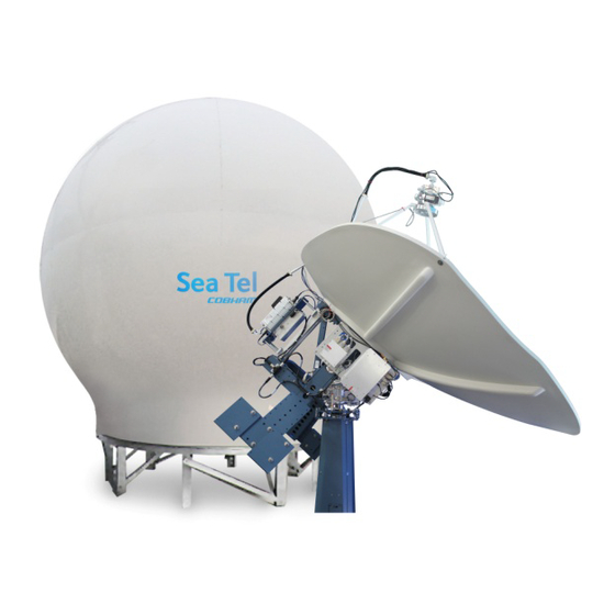
9707D-70 C-BAND TX/RX ANTENNA
WARNING: RF RADIATION HAZARD
This stabilized antenna system is designed to be used with transmit/receive equipment
manufactured by others. Refer to the documentation supplied by the manufacturer which
will describe potential hazards, including exposure to RF radiation, associated with the
improper use of the transmit/receive equipment. Note that the transmit/receive
equipment will operate independently of the stabilized antenna system. Prior to work on
the stabilized antenna system, the power to the transmit/receive system must be locked
out and tagged.
When the transmit/receive system is in operation, no one should be allowed anywhere
within the radiated beam being emitted from the reflector.
The ultimate responsibility for safety rests with the facility operator and the
individuals who work on the system.
Sea Tel Inc doing business as Cobham SATCOM
FOR SEA TEL MODEL
Sea Tel Europe
Unit 1, Orion Industrial Centre
Wide Lane, Swaythling
Southampton, UK S0 18 2HJ
Tel: 44 (0)23 80 671155
Fax: 44 (0)23 80 671166
Email: seatel@cobham.com
Web:
Document. No. 125266 Revision E
www.cobham.com\seatel
Advertisement
Table of Contents
Troubleshooting

Related Manuals for Sea Tel 9707D-70 C-BAND TX


Summary of Contents for Sea Tel 9707D-70 C-BAND TX
- Page 1 Southampton, UK S0 18 2HJ Fax: (925) 798-7986 Tel: 44 (0)23 80 671155 Email: seatel@cobham.com Fax: 44 (0)23 80 671166 Web: : www.cobham.com\seatel Email: seatel@cobham.com Web: www.cobham.com\seatel Sea Tel Inc doing business as Cobham SATCOM December 15, 2009 Document. No. 125266 Revision E...
- Page 2 All Rights Reserved. The information contained in this document is proprietary to Sea Tel, Inc.. This document may not be reproduced or distributed in any form without the consent of Sea Tel, Inc. The information in this document is subject to change without notice.
- Page 4 Revision History ECO# Date Description June 26, 2006 Initial Production Release 5499 September 19, 2007 Change ACU to DAC-2202. Update text and drawings. 6226 June 19, 2008 Update text and drawings to reflect ECO 6226 changes March 4, 2009 Update font, logo, text and drawings December 15, 2009 Updated Text, Graphics, and drawings to reflect current build configuration and GSR2 features...
-
Page 5: Table Of Contents
Table of Contents INTRODUCTION ......................................1-1 1.1..................................1-1 ENERAL YSTEM ESCRIPTION 1.2........................................... 1-1 URPOSE 1.3......................................1-1 YSTEM OMPONENTS 1.4..................................1-2 ENERAL SCOPE OF THIS MANUAL 1.5..................................1-2 UICK VERVIEW OF CONTENTS OPERATION ........................................2-1 2.1....................................... - Page 6 Table of Contents 4.3.4. Preparing BDE Location ................................4-3 4.3.5. Installing The System Cables ..............................4-3 4.4. ADE......................................4-3 SSEMBLING THE 4.4.1. 144” Radome, Baseframe and Antenna Pedestal System Assembly ..............4-3 4.4.2. Preparing the ADE for Lift ................................4-4 4.5.
- Page 7 Table of Contents 7.2.1. Check ACU Parameters ................................7-2 7.2.2. Latitude/Longitude Auto-Update check ..........................7-2 7.2.3. Heading Following ..................................7-2 7.2.4. Azimuth & Elevation Drive ................................. 7-2 7.2.5. Test Tracking ..................................... 7-2 7.2.6. Visual Inspection - Radome & Pedestal .......................... 7-3 7.2.7.
- Page 8 Table of Contents This Page Intentionally Left Blank viii...
-
Page 9: Introduction
9707D-70 C-Band TXRX Introduction Introduction WARNING: RF Radiation Hazard - This stabilized antenna system is designed to be used with transmit/receive equipment manufactured by others. Refer to the documentation supplied by the manufacturer which will describe potential hazards, including exposure to RF radiation, associated with the improper use of the transmit/receive equipment. -
Page 10: General Scope Of This Manual
1.4. General scope of this manual This manual describes the Sea Tel Series 07 Antenna (also called the Above Decks Equipment), its’ operation and installation. Refer to the manual provided with your Antenna Control Unit for its’ installation and operating instructions. -
Page 11: Operation
9707D-70 C-Band TXRX Operation Operation WARNING: RF Radiation Hazard - This stabilized antenna system is designed to be used with transmit/receive equipment manufactured by others. Refer to the documentation supplied by the manufacturer which will describe potential hazards, including exposure to RF radiation, associated with the improper use of the transmit/receive equipment. -
Page 12: Stabilized Pedestal Assembly Operation
Operation 9707D-70 C-Band TXRX 2.4. Stabilized Pedestal Assembly Operation Operation of the stabilized antenna Pedestal Control Unit (PCU) is accomplished remotely by the Antenna Control Unit (ACU). Refer to the Operation section of the Antenna Control Unit manual for more specific operation details. There are no other operating instructions applicable to the pedestal assembly by itself. -
Page 13: Basic System Information
9707D-70 C-Band TXRX Basic System Information Basic System Information This section provides you with some additional information about the satellites you will be using, basics of your Series 07 antenna system and some of the other equipment within your system configuration. 3.1. -
Page 14: Satellite Footprints
Basic System Information 9707D-70 C-Band TXRX 3.1.5. Satellite Footprints The focused beam(s) from the satellites are normally aimed at the major land masses where there are large population centers. Footprint charts graphically display the signal level expected to be received in different geographic locations within the area of coverage. -
Page 15: Tracking Receiver - Single Channel Per Carrier Receiver
9707D-70 C-Band TXRX Basic System Information When the antenna is able to re-acquire the desired signal the ACU will automatically stop searching and begin Tracking the signal to optimize the pointing of the antenna to get the highest signal level from the satellite. 3.2.6. -
Page 16: Components Of The System Configuration
Basic System Information 9707D-70 C-Band TXRX 3.3. Components of the System Configuration Figure 3-1 9707 TXRX Simplified Block Diagram The following text provides a basic functional overview of the system components and component interconnection as referred to in the simplified block diagram for your 9707 antenna. Also, refer to the appropriate page of the System Block Diagram which depicts your system configuration. -
Page 17: Antenna Ade Assembly
9707D-70 C-Band TXRX Basic System Information 3.3.1. Antenna ADE Assembly The Above Decks Equipment consists of an Antenna Pedestal inside a Radome assembly. The pedestal consists of a satellite antenna dish & feed with a linear, or a circular Low Noise Block converter (LNB) with polarization motor mounted on a stabilized antenna pedestal. -
Page 18: Positive Satellite Id
(proper option files) and the ACU/PCU (setup parameters) are actually compatible for the intended satellite(s). 3.5.2. Interface requirements: 3.5.2.1. Hardware Sea Tel Antenna Control Units Model DAC2202 or DAC2302. Any Satellite modem manufacturer that is compatible with OpenAMIP CAT5 Patch cable 3.5.2.2. Software Sea Tel model DAC2202: ACU software version 6.06 or greater... -
Page 19: Utilized Openamip Commands
Set keep alive in seconds (0 = off) “a 5” i s1 s2 Set Antenna Vendor (s1) and device (s2) 2 parameters: “i Sea Tel DAC-2202” s b1 b2 Antenna Status: 2 parameters: “s 1 1” b1 is functional status and b2 is Tx allowed... - Page 20 Basic System Information 9707D-70 C-Band TXRX THIS PAGE INTENTIONALLY LEFT BLANK...
-
Page 21: Installation
9707D-70 C-Band TXRX Installation Installation This section contains instructions for unpacking, final assembly and installation of the equipment. It is highly recommended that final assembly and installation of the Antenna system be performed by trained technicians. Read this complete section before starting. -
Page 22: Site Survey
Installation 9707D-70 C-Band TXRX WARNING: RF Radiation Hazard - This stabilized antenna system is designed to be used with transmit/receive equipment manufactured by others. Refer to the documentation supplied by the manufacturer which will describe potential hazards, including exposure to RF radiation, associated with the improper use of the transmit/receive equipment. -
Page 23: Preparing Bde Location
9707D-70 C-Band TXRX Installation 4.3.4. Preparing BDE Location Prepare the mounting location for the Below Decks Equipment. These equipments would normally be installed in a standard 19” equipment rack. Refer to the Antenna Control Unit manual for installation of the ACU and the Terminal Mounting Strip. -
Page 24: Preparing The Ade For Lift
Installation 9707D-70 C-Band TXRX Loosely assemble the 6 upper side panels, using the hardware provided, to form the upper half of the radome. Do NOT tighten the bolts at this time. Open each seam wide enough to install a good bead of silicone caulk, then firmly tighten all the bolts in that flange. -
Page 25: Install Antenna/Radome/Baseframe
Sea Tel recommends that separate, dedicated, AC Power be provided for the Marine Air Conditioner (Do NOT combine with the AC Power provided for the Antenna Pedestal and RF Equipment). This AC Power cable is routed into the Marine Air Conditioner and terminated to the AC terminals inside. -
Page 26: Remove Stow Braces/Restraints
Installation 9707D-70 C-Band TXRX 4.8.2. Remove Stow Braces/Restraints Remove the restraints from the antenna and verify that the antenna moves freely in azimuth, elevation, and cross level without hitting any flanges on the radome. 4.8.3. Verify all assembly and Wiring connections Verify that all pedestal wiring and cabling is properly dressed and clamped in place. -
Page 27: Setup
9707D-70 C-Band TXRX Setup Setup Below are basic steps to guide you in setting up the ACU for your specific antenna pedestal. Assure that the Antenna Pedestal (ADE) has been properly installed before proceeding. Refer to the Setup section of you ACU manual for additional parameter setting details. -
Page 28: Calibrating Relative Antenna Position (Home Flag Offset)
Setup 9707D-70 C-Band TXRX If no skew is required, start with an initial skew value of 00. While transmitting a pure carrier wave, increment/decrement the SKEW parameter as required to achieve proper Cross-Pol Isolation. Each increment equals one degree of polarization rotation, decrement below 0 for minus polarization. to increment or the DOWN arrow to decrement the value and then hit the ENTER key to adjust the feed to the new value. - Page 29 9707D-70 C-Band TXRX Setup If the antenna stopped before it got to the bow-line; When you initially target a satellite, the antenna will also stop prior to the satellite position, so you that will have to drive the Azimuth of the antenna UP to actually find the satellite.
-
Page 30: To Enter The Hfo Value
Setup 9707D-70 C-Band TXRX 5.5.2. To Enter the HFO value: To enter the calculated HFO value, press & hold both LEFT and RIGHT arrows for six seconds to enter the parameter menu at the EL TRIM parameter window. Press DOWN arrow key numerous times (about 21) until you have selected the REMOTE COMMAND window. -
Page 31: Sat Skew Setting
Setup 9707D-70 C-Band TXRX 5.1. Sat Skew setting The Satellite Skew setting in the Satellite – Tracking Receiver sub-menu (prior to NID) is used to enter the skew of the satellite to optimize polarity angle. This feature will replace the use of POL OFFSET to optimize polarization of the feed. From here on out, POL OFFSET will serve to calibrate the feed itself. -
Page 32: Default Setup Parameters
9707D-70 C-Band TXRX Setup 5.3. Default Setup Parameters The following table shows the factory default parameters for the Antenna Control Unit interfaced to a Series 07 Antenna PCU. When the installation & setup of your system is finished you can record the “optimized” settings for your system in the “My Parameters”... -
Page 33: Functional Testing
Turn ACU power ON. Turn antenna Pedestal/RF Equipment power ON Press RESET on the ACU front panel of the ACU. Verify the display shows "SEA TEL INC - MASTER" and the ACU software version number. Wait 10 seconds for the display to change to "SEA TEL INC - REMOTE" and the PCU software version number. - Page 34 Functional Testing 9707D-70 C-Band TXRX Note the current peak ACG value. Press the Tracking key to toggle Tracking OFF, press the UP arrow key repeatedly to move the antenna up in elevation until AGC falls about 100 counts. Turn Tracking ON and verify that the antenna moves back down in elevation and that the AGC rises to its’...
-
Page 35: Maintenance And Troubleshooting
7.1. Warranty Information Sea Tel Inc. supports its Series 97, 00, 06 and 07 systems with a ONE YEAR warranty on parts and labor. What’s Covered by the Limited Warranty? The Sea Tel Limited Warranty is applicable for parts and labor coverage to the complete antenna system, including all above-decks equipment (radome, pedestal, antenna, motors, electronics, wiring, etc.) and the Antenna Control Unit... -
Page 36: Check Acu Parameters
7.2.5. Test Tracking The 4 Quadrant Tracking Test is one of the best tests that can be performed on any Sea Tel 3-axis antenna. It verifies good antenna operation including antenna drive, ACU receiver operation, and tracking operation. This procedure explains the process of and is HIGHLY RECOMMENDED that this test is performed on ALL antennas that you work on. -
Page 37: Visual Inspection - Radome & Pedestal
9707D-70 C-Band TXRX Maintenance and Troubleshooting LEFT arrow to drive antenna down (CCW) in Azimuth Using the DOWN arrow key to drive antenna down in Elevation Using the UP arrow key to drive antenna up in Elevation Using the 7.2.6. Visual Inspection - Radome &... -
Page 38: Antenna Initialization (Series 97B & Series 00 )
7.3.3. Troubleshooting using DacRemP While troubleshooting a Sea Tel 3-Axis Antenna System, you must classify the fault you are dealing with as a failure within one of 3 major system functions, Targeting, Stabilization, and Tracking. Should there be a failure with any one of these functions, your system will not operate properly. A few simple checks may help determine which fault (if any) that you are dealing with. -
Page 39: Antenna Loop Error Monitoring
9707D-70 C-Band TXRX Maintenance and Troubleshooting Targeting: is the ability to accurately point the antenna to an angular position in free space and is controlled by the ACU. (Does the system drive to the Azimuth, Elevation, and Polarity positions within 1 degree of the desired satellite?) Stabilization: is the process of de-coupling the ships motion from the antenna and is controlled by the PCU. - Page 40 Maintenance and Troubleshooting 9707D-70 C-Band TXRX • • This chart displays sensed axis errors via three traces, CL (Cross Level), LV (Elevation), and AZ (Azimuth), at a fixed 0.05º/ vertical division. • The normal trace average will plots it’s display ± 3 divisions from the red reference line. Any trace line average plotted above this is of concern and troubleshooting required.
-
Page 41: Reference Sensor Monitoring
9707D-70 C-Band TXRX Maintenance and Troubleshooting DishScan Drive turned Off, notice the lack of accumulated IVC errors. 7.3.5. Reference Sensor Monitoring The DacRemP DISPV graph chart provides a means for monitoring the output of the 2 Axis Tilt Sensor and the Home Switch sensor for diagnostic purposes. -
Page 42: Open Loop Rate Sensor Monitoring
Maintenance and Troubleshooting 9707D-70 C-Band TXRX • The Azimuth display for the Home Switch will normally display a logic level high (plots directly on Red reference line after clicking on the button) when the home flag is NOT engaged and changing to a logic level low when engaged. -
Page 43: Open Loop Motor Test
9707D-70 C-Band TXRX Maintenance and Troubleshooting sensor output is, for the most part restricted to a positive or negative response of the Level Cage movement (plotting above or below the red reference line of each axis). 7.3.7. Open Loop Motor Test The DacRemP Comm Diagnostics Window provides a means to enter in Remote Commands for driving each individual torque motor to test that motors functionality. -
Page 44: Satellite Reference Mode
Maintenance and Troubleshooting 9707D-70 C-Band TXRX 7.3.9. Satellite Reference Mode The ships gyro compass input to the ACU may be accurate and stable in static conditions and yet may NOT be accurate or stable enough in some underway dynamic conditions. If there is no gyro compass or if the input is corrupt, not stable or not consistently accurate the tracking errors will become large enough to cause the antenna to be mis-pointed off satellite. - Page 45 9707D-70 C-Band TXRX Maintenance and Troubleshooting Left mouse click on the icon. Right mouse click on the icon. This will display a list box with the status of the above decks pedestal filtered into 3 sections. Items preceded with a check marks indicate a flagged status.
-
Page 46: Remote Gps Lat/Lon Position
Maintenance and Troubleshooting 9707D-70 C-Band TXRX PCU Status (Word 2) Az Target Indicates the antenna is currently targeting a pre-determined azimuth position Az Velocity **Not a valid state** Valid Heading (PCU) Indicates that the PCU has received and integrated the heading value from the ACU into the Azimuth Stabilization Loop. - Page 47 Furuno default value is in Japan at 34.4N 135.2E (@3444,N,13521,E,,_). After acquiring a good fix at Sea Tel the string is @3800,N,12202,W,A^ for our 38N 122W Latitude and Longitude position. The status character tells you the status of the GPS.
-
Page 48: Maintenance
Maintenance and Troubleshooting 9707D-70 C-Band TXRX “,” (Comma) = GPS has NOT acquired a proper fix, “N” = GPS fix is NOT valid “A” = GPS has acquired a valid fix. 7.4. Maintenance 7.4.1. Balancing the Antenna The antenna and equipment frame are balanced at the factory however, after disassembly for shipping or maintenance, balance adjustment may be necessary. -
Page 49: To Adjust Tilt
9707D-70 C-Band TXRX Maintenance and Troubleshooting Rotate the feed CCW 180 degrees or as far as it will travel, viewed looking towards the satellite (CW looking into the dish). If the feed allows full 180-degree rotation, the POL display will show 90 counts below the center reference value. -
Page 50: 7.4.4. To Reset/Reinitialize The Antenna
Maintenance and Troubleshooting 9707D-70 C-Band TXRX Step 3: On the ACU front Panel, press either the ENTER key or the DOWN arrow key until the REMOTE TILT window is displayed Step 4: Push the RIGHT arrow key to activate the Remote Tilt Mode. Step 5: Based on the feedback from the technician observing the circular bubble, the technician which operating the ACU will need to use the arrow keys to rotate the stabilized antenna mass from front to... -
Page 51: Pedestal Control Unit Configuration - 9707
9707D-70 C-Band TXRX Maintenance and Troubleshooting Using the LEFT/RIGHT and UP/DOWN arrow keys set the Remote Command value to "^0090" and press ENTER. This resets the PCU on the antenna. The antenna will reinitialize with this command (Performs a similar function as a power reset of the antenna). - Page 52 Maintenance and Troubleshooting 9707D-70 C-Band TXRX Last, balance the antenna with the elevation pointed at, or near, zenith (referred to as top to bottom balance) by moving existing counter-weights from the top to the bottom or from the bottom to the top. Always move weight from one location on the equipment frame to the same location on the opposite side of the equipment frame (ie from the top left of the reflector mounting frame to the bottom left of the reflector mounting frame).
-
Page 53: 9707D-70 Technical Specifications
9707D-70 C-Band TXRX 9707D-70 Technical Specifications 9707D-70 Technical Specifications The technical specifications for your Series 07 Above Decks Equipment subsystems are listed below: Refer to your ACU manual for its’ Specifications. 8.1. Antenna Reflector Type Honeycomb Fiberglass Parabola Diameter (D) 2.4 Meter Modified Offset Sidelobe: Compliant with Intelsat Standard G... -
Page 54: Stabilized Antenna Pedestal Assembly
9707D-70 Technical Specifications 9707D-70 C-Band TXRX 8.4. Stabilized Antenna Pedestal Assembly Type: Three-axis (Level, Cross Level and Azimuth) Stabilization: Torque Mode Servo Stab Accuracy: 0.2 degrees MAX, 0.1 degrees RMS in presence of specified ship motions (see below). LV, CL, AZ motors: Size 34 Brushless DC Servo. -
Page 55: Unlimited Azimuth Modems (3 Channel) L-Band If
Withstand relative average winds up to 100 MPH from any direction. Ingress Protection Rating All Sea Tel radomes have an IP rating of 56 NOTE: Radome panels can absorb up to 50% moisture by weight. Soaked panels will also have higher attenuation. -
Page 56: Txrx System Cables
8.9.2. Antenna Transmit & Receive IF Coax Cables (Customer Furnished) Due to the dB losses across the length of the RF coaxes at L-Band, Sea Tel recommends the following 50 ohm coax cable types (and their equivalent conductor size) for our standard pedestal installations:... -
Page 57: Drawings
9707D-70 C-Band TXRX Drawings Drawings The drawings listed below are provided as a part of this manual for use as diagnostic reference. 9.1. 9707D-70 Model Specific Drawings Drawing Title 128390-1_B4 System, Model 9707D-70, C-Circular, A/C 125075-3_G System Block Diagram – Model 9707D-70 128389-1_A General Assembly –... - Page 58 Drawings 9707D-70 C-Band TXRX This Page Intentionally Left Blank...
- Page 59 SINGLE LEVEL MFG BILL OF MATERIAL FIND QTY PART NO REV DESCRIPTION REFERENCE DESIGNATOR 1 EA 128389-1 GENERAL ASS'Y, 9707D-70 1 EA 111365-17 N1 RADOME ASS'Y, 144 INCH, WHITE/SIDE AC 1 EA 123723-1 B1 RADOME BASE ASS'Y, 75 IN., STL, NO AC 1 EA 124571-2 SSPB, C-BAND, CODAN MBUC, 25W, 6725-W 1 EA 124556-3...
- Page 61 SINGLE LEVEL MFG BILL OF MATERIAL FIND QTY PART NO REV DESCRIPTION REFERENCE DESIGNATOR 1 EA 128389-1 GENERAL ASS'Y, 9707D-70 1 EA 111365-X (REF ONLY) RADOME ASS'Y, 144 INCH 1 EA 125498-1 FEED ASS'Y, C-BAND, CIRCULAR, DISHSCA 1 EA 124571-X (REF ONLY) SSPB, C-BAND, MBUC, CODAN 1 EA 124556-X (REF ONLY) LNB, C-BAND PLL, NORSAT 30...
- Page 62 SINGLE LEVEL MFG BILL OF MATERIAL FIND QTY PART NO REV DESCRIPTION REFERENCE DESIGNATOR 1 EA 113303-10 T1 CABLE ASS'Y, SMA 90 - SMA (M), 8 IN 2 EA 114972-2 M CABLE ASS'Y, SMA(M) - SMA(M), 72 IN 1 EA 121281 CABLE ASS'Y, SMA(F)-SMA(M), 3 IN.
- Page 64 SINGLE LEVEL MFG BILL OF MATERIAL FIND QTY PART NO REV DESCRIPTION REFERENCE DESIGNATOR 1 EA 128144-1 A2 PEDESTAL ASS'Y, XX07 1 EA 121605-4 F1 POWER ASS'Y, 220V, 34 IN. SINGLE SHRO 1 EA 125074-1 EQUIPMENT FRAME ASS'Y, XX07 1 EA 116803 REFLECTOR, OFFSET, 2.4M 1 EA 120292 D1 FEED STRUT, TOP...
- Page 67 SINGLE LEVEL MFG BILL OF MATERIAL FIND QTY PART NO REV DESCRIPTION REFERENCE DESIGNATOR 1 EA 117696-2 WAVEGUIDE, WR-229, 90 DEG E-BEND 1 EA 129948-1 A2 C BAND RADAR TRANSMIT REJECT FILTER 1 EA 117507 WAVEGUIDE, WR-137, 20 DEG E-BEND 1 EA 123283 A2 FEED, C-BAND, CIRCULAR, DISHSCAN, TUN 2 EA 123618-37...
- Page 71 SINGLE LEVEL MFG BILL OF MATERIAL FIND QTY PART NO REV DESCRIPTION REFERENCE DESIGNATOR 1 EA 109119-17 F2 RADOME FAB ASS'Y, 144 INCH, WHITE/SID 3 EA 124903-1 B1 STRAIN RELIEF ASS'Y 0 EA 114586-538 SCREW, HEX HD, 1/4-20 x 1, S.S. INCLUDED IN HARDWARE 0 EA 114586-541 SCREW, HEX HD, 1/4-20 x 1-1/2, S.S.
- Page 73 SINGLE LEVEL MFG BILL OF MATERIAL FIND QTY PART NO REV DESCRIPTION REFERENCE DESIGNATOR 1 EA 123724-1 RADOME BASE FRAME ASS'Y, 75 IN, STEEL 1 EA 124458-1 X1 RADOME BASE PAN FAB, WHITE, W/EXTERNA 1 EA 123728-2 RADOME PAN ACCESS ASS'Y, WHITE 1 EA 123729-1 A/C INSTALL ASS'Y, EXTERNAL 6 EA 114586-540...
- Page 74 NOTES: (UNLESS OTHERWISE SPECIFIED) 1-14-05 RELEASED TO PRODUCTION NONE 04-13-05 -9 ADDED 1. APPLY ADHESIVE PER SEA TEL SPEC. 121730. NONE 04-29-05 -9 BASE FRAME WS STL. LG. FOOT, BASE PAN WS P/N 123726-2 4888 05-31-05 FOR -5, -6, -8, -9 BASE PAN WAS P/N 123726-1.
- Page 75 SINGLE LEVEL MFG BILL OF MATERIAL FIND QTY PART NO REV DESCRIPTION REFERENCE DESIGNATOR 1 EA 116941 STREET ELBOW, 1/2 INCH 1 EA 116938 FLEX HOSE, 1/2 INCH 2 EA 124903-1 B1 STRAIN RELIEF ASS'Y 1 EA 121008-72 D2 CABLE ASS'Y, AC INPUT, 72 IN. (SPADE (NOT SHOWN) 4 EA 120470 ISOLATORS, BUMPER...
- Page 77 REVISION HISTORY REV ECO# DATE DESCRIPTION 4609 10-05-04 RELEASED TO PRODUCTION 4858 5-5-05 ADD REFERENCE 121113 3-2-06 CHANGED TO TABLE FORMAT V.S. CONTROL PANEL 1-9-07 CREATED CAD OUTLINE DRAWING 17.85 12.80 AIR FLOW 2.53 31.88 33.00 18 MAX 30.00 1.50 15.25 15.9 INLET...
- Page 79 SINGLE LEVEL MFG BILL OF MATERIAL FIND QTY PART NO REV DESCRIPTION REFERENCE DESIGNATOR 1 EA 112657 D MACHINING, TERMINAL MOUNTING STRIP 1 EA 126865-2 PCB ASS'Y, TERMINAL MOUNTING STRIP, 5 1 EA 112936-36 D1 CABLE ASS'Y, D-SDB, 25 PIN, 36 IN 1 EA 116669-36 B1 CABLE ASS'Y, D-SUB, 9-PIN, 36 IN.
- Page 82 SINGLE LEVEL MFG BILL OF MATERIAL FIND QTY PART NO REV DESCRIPTION REFERENCE DESIGNATOR 1 EA 116880 G PANEL MACHINING, RACK, BASE MUX 1 EA 117168-2 P1 MODEM ASS'Y, BASE, 3 CH, 75 OHM 1 EA 117611-4 H MODEM ASS'Y, BASE, 3 CH, 50 OHM 1 EA 116388 D BRACKET, CONNECTOR 1 EA 115492-1...
Need help?
Do you have a question about the 9707D-70 C-BAND TX and is the answer not in the manual?
Questions and answers