Table of Contents
Advertisement
Quick Links
E
strella
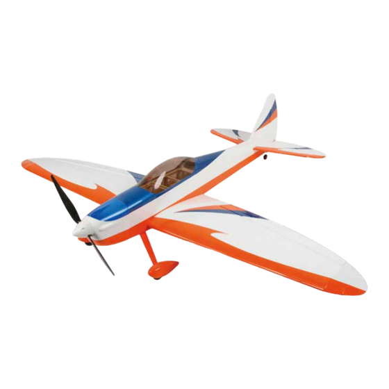
The new Estrella Sport-50E ARF, was designed in an extremely lightweight structure, the all wood
airframe with refreshing colors cover. Low-wing design is easy to fly for training. This is the electric
motor assembly manual, but we still provide the engine mount and the fuel tank spare parts. In case
when you became a good player you can change to the methanol engine power.
The Estrella Sport-50E will bring you the flying sky, if you want to fly and just do it.
.....without any aerobatic limit when you fantasy to do it !
Specifications:
Wingspan:
1500mm (59in)
Length:
1322mm (52in)
Wing Area:
40.8 sq dm
S
Weight:
2.5-3.0kg(5.5-6.5lb)
Radio:
4-channel w/4-5 servos
Engine:
40-52 2-stroke; 56-82 4-stroke; Power 46
port
ARF
Advertisement
Table of Contents

Related Manuals for HobbyKing Estrella Sport-50E


Summary of Contents for HobbyKing Estrella Sport-50E
- Page 1 The Estrella Sport-50E will bring you the flying sky, if you want to fly and just do it..without any aerobatic limit when you fantasy to do it !
-
Page 2: Table Of Contents
Table of contents Required radio, motor and battery ..............3 Additional required items, tools and adhesives ...........3 Warning ......................3 Before starting assembly ..................3 Using the manual ....................4 Section 1 – ailerons installation .................5 Section 2 – aileron servo & control horn installation ..........6 Section 3 –elevator installation ...............8... -
Page 3: Required Radio, Motor And Battery
Before starting assembly Before starting the assembly of your Little Estrella Sport-50E, remove each part from its bag and protection for a prior inspection Closely inspect the fuselage, wing panels, rudder, and stabilizer for damage. If you find any damage or missing parts, contact the place of purchase. If you find any wrinkles in the covering, use a heat gun or covering iron to remove them. -
Page 4: Using The Manual
14. Wheel cowling 15. Aluminium landing gear Main landing gear system parts Tail wheel system parts 2mm Tail wheel bracket 1pcs Estrella Sport-50E 1"PU tail wheel 1pcs M3×12mm(12.9)Socket Head Screws 6pcs T2*8mm self-tapping screw 4pcs Parts 2mmTail Wheel Bracket Wire 1pcs ∮... -
Page 5: Section 1 - Ailerons Installation
strella port Section 1 – ailerons installation Required Parts Main Wing (Right & Left) Aileron(Right & Left) Eight Hinges (Right & Left) Tools and Adhesives Hobby knife Thin CA □□ step 1 Trial fit the four aileron hinges, included in the hardware pack, in their place and verify the correct position and alignment of the aileron with the wing panel. -
Page 6: Section 2 - Aileron Servo & Control Horn Installation
Section 2 – aileron servo & control horn installation Required Parts 2 ServoCover Plate (Right & Left) 4 ServoFixationBlock (Right & Left) 8 T2*8mmSelf-tappingScrewWith ShoulderWasher(Right & Left) 2 Black Epoxy RockerArm (Right & Left) 2 Black Epoxy Horn and pedestal (Right&... - Page 7 strella port □□ step 4 Put the pre-installation servo into the wing panel,as per picture.
-
Page 8: Section 3 -Elevator Installation
□□ step6 Install the push and pull rod connecting rod,and use the four T2*8mm Self-tapping Screw With Shoulder Washer to fix the servo cover plate. □ step 7 Repeat steps 1 through 6 for the remaining wing panel. Section 3 – elevator installation Required Parts 1horizontal tai 1 Elevator 6 Hinges 1 Elevator connect steel wire... - Page 9 strella port □ step 2 Insert the elevator Connector through the fuselage □ step 3 Insert the horizontal tail into fuselage space and locate the elevator hinges into the horizontal tail □□ step 4 Glue carefully the hinges in the horizontal tail and elevator with some drops of thin CA.
-
Page 10: Section 4 -Rudder Installation & Tail Wheel Installation
□ step 5 Carefully check the balance of the horizontal tail with the fuselage, as per pictures. □ step 6 Once satisfied with the balance, glue carefully with thin CA the horizontal tail at the fuselage. Section4 – rudder installation & tail wheel installation Required Parts 1 Rudder 1 Vertical fin 3 Hinges... - Page 11 strella port □ step 2 Inset three hinges into the rudder ,than install the tail wheel system, as picture shown. □ step 3 Install the vertical fin to the fuselage, make sure the vertical perpendicular to horizontal tail. □ step4 Use a oil pen to make remark line on vertical fin, take out it and use a hobby knife to cut off the cover, as the picture show.
-
Page 12: Section 5 -Landing Gear & Wheels Installation
□ step5 Install the vertical fin to the fuselage and use CA the glue it well, as picture show. □ step 6 Install the rudder to the vertical fin, and glue each hinges with thin CA. Section 5 – landing gear & wheels installation Required Parts 1 Pair AluminumMain LandingGear 2 2.25”Pu wheel... - Page 13 strella port □ step1 Locate the following items included in the hardware pack. □ step 2 The main landing gear is mounted to the bottom of the fuselage using three M3*12 Socket Head Cap Screw and threeΦ3.1mm Flat Washer. Apply a drop of threadlock on each of the screws. Use a 3mm hex wrench to tighten the screws to secure the landing gear to the bottom of the fuselage.
- Page 14 □□ step 5 Slide the wheel on the axle. Use a 5/32-inch wheel collar and a 3mm x 5mm machine screw to secure the collar. Make sure to position the collar so the wheel can rotate freely on the axle. Use a #2 Phillips screwdriver to tighten the screw on the flat area of the axle.
-
Page 15: Section 6- Elevator Servo & Control Horn Installation
strella port Section 6– elevator servo & control horn installation Required Parts 1 F 2*690mm P ushrod (elevator) 1 N ylon Pushrod keeper 1 M2*10mm S ocket Head C ap S crew 1 M2 Lock nut 1 Black Epoxy Horn with pedestal 1 Nylon ball joint Tools and Adhesives Socket head screw wrench 1.5mm... - Page 16 □ step 5 Put elevator push rod(with screw thread side) through the elevator Pushrod tube hole, reach the elevator horn position ,as picture shown. □ step 6 Use the nylon ball joint to proofread the distance between the rudder push rod and the horn, as picture shown. □...
- Page 17 strella port □ step 9 Cut the redundant length of the push rod, as the picture shown. □ step 10 Install the elevator push rod into the push rod tube again, and use the Nylon Pushrod keeper to lock the push rod in the elevator horn.
-
Page 18: Section 7 - Rudder Servo & Control Horn Installation
Section 7 – rudder servo & control horn installation Required Parts 1 F 2*690mm P ushrod (elevator) 1 N ylon Pushrod keeper 1 M2*10mm S ocket Head C ap S crew 1 M2 Lock nut 1 Black Epoxy Horn with pedestal 1 Nylon ball joint Tools and Adhesives Socket head screw wrench 1.5mm... - Page 19 strella port □ step 5 Put rudder push rod(with screw thread side) through the rudder pushrod tube hole, reach the rudder horn position ,as picture shown. □ step 6 Use the nylon ball joint to proofread the distance between the rudder push rod and the horn, as picture shown. □...
-
Page 20: Section 8 - Electric Motor Installation
□ step 10ElevatorInstall the rudder push rod into the push rod tube again, and use the Nylon Pushrod keeper to lock the push rod in the rudder servo horn. Elevator Rudder □ step 11 Up side down the fuselage and install the ball joint to the rudder push rod and the rudder horn, as the picture shown. - Page 21 strella port □ step 3 Use a 5.5mm drill bit to dill four holes, as the picture shown. □ step 4 Fix the four Blind Nuts into the four holes Paint some 30 min epoxy on the blind nut. Install the blind nut on the firewall holes, as the picture show.
-
Page 22: Section9 -Electronic Speed Controller And His Switch And Battery Installation
□ step 5 Use 3mm hex wrench or ball driver to install the motor(need to buy) on the fire wall, as the picture shown. Screw the blind nut into the firewall wood, as picture show. Section9 –electronic speed controller and his switch and battery installation □... - Page 23 strella port □ step4 Insert the battery tray in the fuselage with the speed control facing to the fuselage, □ step5 Use a hobby knife to chip-off the cover of the switch position, as the picture shown.
-
Page 24: Section 10 - Final Radio Installation
Section 10 – final radio installation Install the receiver, as the picture shown. Section 11 – wings installation □ step1 Install the wood tube into the main wing, as the picture shown. □ step2 Upside down the fuselage, install the wing in to the fuselage, as picture show. -
Page 25: Section 12 -Cockpit Canopy Installation
strella port □ step2 Find the past in the hardware pack to retaining the wing, as picture shown. Section 12 –cockpit canopy installation □ step1 The cockpit canopy installation as the picture show. Lock the canopy well. Section 13 – cowl installation □□... - Page 26 □□ step 2 Apply a piece of masking tape on the cowl , than mark the position as per the picture. □□ step 3 Use a 2mm drill bit to drill the screw holes, as picture show. □□ step 4 Attach the cowl using the four T2*8mm self-tapping screws with shoulder washer, included in hardware pack, with a Phillips screwdriver.
-
Page 27: Control Throws
strella port □ step 5 Fix carefully the prop and the spinner as per picture. Control Throws □ Step 1 Turn on the transmitter and receiver of your model. Check the movement of the rudder using the transmitter. When the stick is moved right, the rudder should also move right. Reverse the direction of the servo at the transmitter if necessary. -
Page 28: Center Of Gravity(Cg)
Center of Gravity(CG) An important part of preparing the aircraft for flight is properly balancing the model. Caution: Do not inadvertently skip this step! The recommended Center of Gravity (CG) location for the your model is 43/4-inch (120mm) back, or 25% of the chord, from the leading edge of the wing.
Need help?
Do you have a question about the Estrella Sport-50E and is the answer not in the manual?
Questions and answers