
Related Manuals for Sigma 1-15PK


Summary of Contents for Sigma 1-15PK
- Page 1 Operating Manual Refrigerated Centrifuge 1-15PK from serial no. 120506 Please retain for later use!
- Page 3 In case of inquiries please state the following number: Serial number: © Copyright by Sigma Laborzentrifugen GmbH An der Unteren Söse 50 37520 Osterode am Harz Germany Phone +49 (0) 55 22 / 50 07-0 +49 (0) 55 22 / 50 07-12 E-mail: info@sigma-zentrifugen.de...
-
Page 7: Table Of Contents
Table of Contents General Information Importance of the Operating Manual Intended Use Technical Data 1.3.1 Ambient Temperature Scope of Supply Standards and Regulations Safety Instructions and Hazard Warnings Symbols used in the Safety Instructions Symbols used in the Operating Manual Informal Notes on Safety Safety Instructions for Centrifugation 2.4.1 Special Instructions... - Page 8 Using the Centrifuge Description 5.1.1 Operating Elements 5.1.1.1 Operating Panel 5.1.1.2 Name Plate 5.1.2 Construction and Constructive Safety Measures 5.1.3 Drive 5.1.4 Operation and Display 5.1.5 Electronic System 5.1.6 Safety Devices 5.1.6.1 Lid Lock and Lid Closing Device 5.1.6.2 Standstill Monitoring 5.1.6.3 System Check 5.1.6.4 Ground Wire Check 5.1.6.5 Imbalance Monitoring System...
- Page 9 5.3.3 Relative Centrifugal Force (RCF) 5.3.3.1 Changing the RCF Increments 5.3.4 Temperature 5.3.4.1 Precooling 5.3.5 Rotors 5.3.6 Program 5.3.6.1 Saving the Current Settings 5.3.6.2 Calling Up Stored Programs 5.3.7 Lockdown 5.3.7.1 Permanent Lockdown 5.3.8 Activating/Deactivating the Automatic Lid Opening Function 5.3.9 Activating/Deactivating the Sound Signal Malfunctions and Error Correction Error Mode...
- Page 10 Care and Maintenance Cleaning and Care Centrifuge 7.1.1 7.1.2 Accessories 7.1.2.1 Plastic Accessories 7.1.2.2 Aluminum Accessories 7.1.3 Rotor, Buckets, and Multiple Carriers 7.1.3.1 Microhematocrite Rotor 7.1.4 Load-bearing Bolts 7.1.5 Glass Breakage 7.1.6 Condenser Sterilization and Disinfection of the Rotor Chamber and Accessories 7.2.1 Autoclaving Disposal Disposal of the Centrifuge...
-
Page 11: General Information
(see BGR 500, chapter 2.11, part 3). They are solely intended for this purpose. Any other use beyond this area of application is regarded as improper use. SIGMA Laborzentrifugen GmbH cannot be held liable for any damage resulting from such improper use. -
Page 13: Technical Data
Technical Data Manufacturer: S I G M A Laborzentrifugen GmbH An der Unteren Söse 50 37520 Osterode Type: 1-15PK Electr. connection: See name plate Protection class: IP code: Connected load (kVA): Power consumption (kW): 0.63 Max. current consumption (A): 3.4 (at 220-240 V / 50-60 Hz) 6.8 (at 120 V / 60 Hz) -
Page 15: Scope Of Supply
Scope of Supply The centrifuge comprises: • 1 connecting cable depending on the voltage variant • 1 rotor wrench Part no. 930 050 • 20 ml slushing oil Part no. 70 104 • 1 tube of grease for load bearing bolts Part no. -
Page 16: Safety Instructions And Hazard Warnings
Surface chaude Nicht mit dem Hausmüll entsorgen Do not dispose as part of domestic waste Ne pas jeter avec les déchets ménager Fig. 2.1: Symbols used for SIGMA centrifuges Version 08/2008, Rev. 1.7 - sb page 16 of 75 English translation... -
Page 17: Symbols Used In The Operating Manual
Symbols used in the Operating Manual Symbols used in the Operating Manual: Symbol Title Gefährliche elektrische Spannung Dangerous voltage Courant haute tension Achtung, mögliche gefährliche Situation Attention, potentially dangerous situation Attention, situation potentiellement dangereuse Hinweis auf wichtige Sachverhalte Note concerning important facts Attention! Information très importante Fig. -
Page 18: Safety Instructions For Centrifugation
When not using the centrifuge, open the lid so that all liquids can evaporate. • Stop the centrifuge immediately in the event of a malfunction. Eliminate the problem (see 6.2, page 46 ff) or inform the SIGMA Laborzentrifugen GmbH service team (see 6.2.9 "Service Contact", page 49). Version 08/2008, Rev. 1.7 - sb... -
Page 19: Resistance Of Plastics
2.4.2 Resistance of Plastics Chemical influences have a strong effect on the polymeric chains of plastics, and therefore, on their physical properties. Plastic parts can be damaged if solvents, acids, or alkaline solutions are used. • Please refer to the resistance table (see 11.3, page 69)! Prohibited Centrifuging Operations and Hazard Warnings Under the rules stipulated by the German trade association BGR 500, chapter 2.11, part 3, the operator is obliged to:... -
Page 20: Special Hazards
• Do not spin any substances that could damage the material of the rotors and buckets of the centrifuge in any way. Highly corrosive substances, for example, damage the material and affect the mechanical strength of the rotors and buckets. •... -
Page 21: Checks By The Operator
Checks by the Operator Check all of the safety-relevant parts of the centrifuge at least once per month for any visible signs of damage (e.g. cracks, corrosion). This applies particularly to the following: • Concentricity of the motor shaft: − Visual inspection: Slowly rotate the rotor by hand without the rotor tie- down screw. -
Page 22: Transport And Storage
Transport and Storage Dimensions and Weight Depth: 575 mm Width: 365 mm Height: 300 mm Weight: 41 kg Fig.3.1: Dimensions and weight Notes on Transport • Always lift the centrifuge with a lifting device or with a sufficient number of people helping you. -
Page 23: Set-Up And Connection
Please retain the packaging for any possible future transport of the centrifuge. 4.1.1 Transport Safety Device The transport safety device of the SIGMA 1-15PK consists of a screw which is located at the bottom panel. Attention! The transport safety device must be removed prior to start-up because the... -
Page 24: Installation
The operating voltage on the name plate must correspond to the local supply voltage! SIGMA laboratory centrifuges are units of safety class I and have a three-wire power cord with a IEC C13 connector. On the back, next to the mains power input, there is an additional ground wire connector (see Fig. -
Page 25: Using The Centrifuge
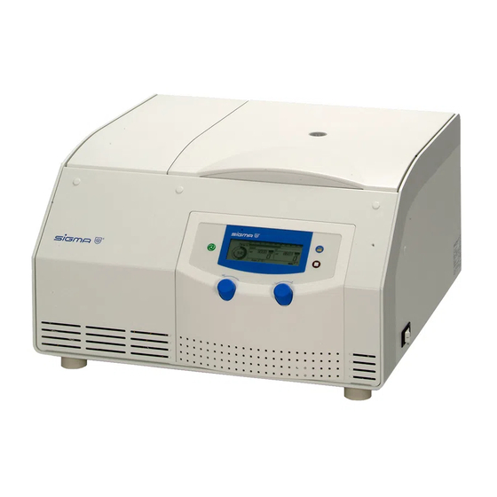
Using the Centrifuge Description 5.1.1 Operating Elements 1 Lid 2 Start key 3 Left rotary knob 4 Right rotary knob 5 Stop key 6 Lid key 7 Display Fig. 5.1: total view of the centrifuge 8 Programming connector at the bottom plate (only for service purposes) Fig. -
Page 26: Operating Panel
5.1.1.1 Operating Panel Start key Time display Temperaturskala Speed display RCF display Lid key Stop key Display for rotor, deceleration curves and programs Rotary knobs Fig. 5.4: Operating panel with centrifuge display The centrifuge is started directly via the operating panel. When the centrifuge is switched on, all of the operating keys and displays will be illuminated for a short time. -
Page 27: Construction And Constructive Safety Measures
5.1.2 Construction and Constructive Safety Measures The centrifuge is installed within a solid construction. On the back, the lid is secured by solid hinges and on the front by two separate lid locks. 5.1.3 Drive The drive motor is a well-dimensioned, collector-less asynchronous motor. 5.1.4 Operation and Display The display is a hermetically sealed LCD display. -
Page 28: Safety Devices
5.1.6 Safety Devices Apart from the mentioned passive safety devices due to the solid design, the following active precautions are in place for your safety: 5.1.6.1 Lid Lock and Lid Closing Device The centrifuge can only be started when the lid is properly closed. The electrical locks must be locked. -
Page 29: Initial Start-Up
Initial Start-Up Before the initial start-up, please ensure that your centrifuge is properly set up and installed (see 4.2 "Installation", page 24). 5.2.1 Switching the Centrifuge ON • Press the mains power switch on the back side (see Fig. 5.3, page 25). The centrifuge display then illuminates. -
Page 30: Installation Of Rotors
5.2.3 Installation of Rotors • Open the centrifuge lid by pressing the lid key. • Unscrew the rotor tie-down screw from the motor shaft (anti-clockwise). • Lower the rotor with its central bore straight down onto the motor shaft. • Tighten the rotor tie-down screw clockwise with the supplied rotor wrench with 5 Nm. -
Page 31: Installation Of Angle Rotors With A Hermetically Sealed Lid
5.2.3.1 Installation of Angle Rotors with a Hermetically Sealed Lid • Screw the rotor cover onto the rotor and tighten it. • Lower the rotor with the cover onto the motor shaft. • Insert the rotor tie-down screw into the motor shaft. Tighten the rotor tie-down screw at 5 Nm using the supplied rotor wrench. -
Page 32: Installation Of The Microhematocrite Rotor
5.2.3.2 Installation of the Microhematocrite Rotor • Lower the microhematocrite rotor with its central bore straight down onto the motor shaft. • Tighten the rotor tie-down screw clockwise with the supplied rotor wrench. In doing so, hold the microhematocrite rotor with your left hand and tilt it slightly, if necessary, in order to prevent the motor shaft from slipping through. -
Page 33: Installation Of Accessories
5.2.4 Installation of Accessories • Only use vessels that are suitable for the rotor (see chapter 10 "Suitable Accessories", page 57). • Load all of the compartments of the swing-out rotors. • Always load the opposite compartments of the rotors with the same accessories and filling to avoid imbalance. -
Page 34: Tubes
5.2.4.1 Tubes • Load the tubes outside of the centrifuge. Liquids in the buckets or multiple carriers cause corrosion. • Fill the tubes carefully and arrange them according to their weight. Imbalances result in the excessive wear of the bearings. •... -
Page 35: Starting The Centrifuge
5.2.6 Starting the Centrifuge The centrifuge is ready for operation when the start key is illuminated. • Press the start key in order to start a centrifugation run. 5.2.7 Interrupting a Centrifugation Run • Press the stop key in order to interrupt a centrifugation run. The centrifugation run will be terminated prematurely. -
Page 36: Display / Program Options
Display / Program Options Fig. 5.10: Display completely active The centrifuge display has the following display fields: Time field "Lock" symbol for lockdown Temperature field Speed field RCF field Field for rotor selection, imbalance indication, run mode, and program selection 5.3.1 Time The runtime of the centrifuge can be set at different intervals in a range from... -
Page 37: Changing The Time Increments
5.3.1.1 Changing the Time Increments In order to change the time in steps of 1 second (instead of in steps of 10 seconds in the min:sec mode) or in steps of 1 minute (instead of in steps of 10 minutes in the hrs:min mode): •... -
Page 38: Speed
5.3.2 Speed The desired speed of the centrifuge (revolutions per minute) can be set here (15,000 rpm in the example shown below). When the maximum permissible speed of the rotor is reached, the “max” display lights up. To preselect a speed value: •... -
Page 39: Relative Centrifugal Force (Rcf)
5.3.3 Relative Centrifugal Force (RCF) The relative centrifugal force (RCF) is the acceleration that the sample is subject The RCF value is determined by the rotor geometry and speed. The RCF and speed values, therefore, depend on each other. When the maximum permissible RCF value of the rotor is reached, the "max"... -
Page 40: Temperature
5.3.4 Temperature The temperature of the centrifuge is controlled by a refrigeration unit. Temperatures between -10 °C and + 40 °C can be preselected. To preselect the temperature in steps of 1 °C: • Turn the left rotary knob until “set” appears in the display field in front of the parameter "Temp"... -
Page 41: Precooling
5.3.4.1 Precooling Depending on the substances to be centrifuged, it may make sense to precool the centrifuge. The precooling prevents the cooled samples in the uncooled centrifuge from heating up to an inadmissible temperature. Precooling at a standstill Unmoved air in the centrifuge chamber distorts the measuring and control behavior and causes the compressor to freeze overs. -
Page 42: Rotors
Info! The automatic lid opening function is suppressed after a rapid cooling phase in order to prevent the system from reheating. Attention! The temperature value indicates the air temperature in the rotor chamber. Please bear in mind that the rotor – depending on its type – will reach this temperature only after a corresponding precooling time. -
Page 43: Program
5.3.6 Program The program is used to save or load certain recurrent settings of the centrifuge. This saves time and prevents typing errors. 50 different programs can be saved and called up. This is only possible at a standstill. 5.3.6.1 Saving the Current Settings To save the current settings: •... -
Page 44: Lockdown
5.3.7 Lockdown This function locks the parameters against all inadvertent changes. • Turn the left rotary knob until a padlock symbol is displayed in the upper left corner of the display (Fig. 5.23). As long as the padlock symbol is displayed, the parameters cannot be changed. 5.3.7.1 Permanent Lockdown The parameter settings can also be locked with the help of the start key when the lid is open:... -
Page 45: Activating/Deactivating The Sound Signal
5.3.9 Activating/Deactivating the Sound Signal If this function is active, a sound signal can be heard at the end of the operation as well as in the event of an error message or imbalance. • Press the lid key five times and on the fifth time hold it down for approx. two seconds. -
Page 46: Malfunctions And Error Correction
Malfunctions and Error Correction Error Mode Malfunctions are indicated by error messages with a number in the speed and rcf display. If the sound signal is activated, it sounds when the error message is displayed (see 5.3.9 "Activating/Deactivating the Sound Signal", page 45). Error Correction •... -
Page 47: Lid Cannot Be Opened
6.2.5 Lid cannot be opened − When first trying to open the lid, • Close the lid again. Press down both the locks are not released. Lid sides of the lid until the locks audibly key LED flashes. lock. Open the lid again. If the error occurs again, unlock the lid manually (see 6.2.7 "Emergency lid release", page 47) and call the service. -
Page 48: Error Codes
6.2.8 Error Codes Error no. Kind of error Measure Note System error allow to slow down All these errors stop power off/on the centrifuge or cause it to slow down. 10-19 Speedometer error allow to slow down power off/on 20-29 Motor error power off/on ensure ventilation... -
Page 49: Service Contact
→ [Contacts] → [Service requests] www.sigma-zentrifugen.de • or contact SIGMA Laborzentrifugen GmbH An der Unteren Söse 50 37520 Osterode (Germany) Tel. +49 (0) 55 22 / 50 07-8425 Fax +49 (0) 55 22 / 50 07-9425 E-mail: service@sigma-zentrifugen.de... -
Page 50: Care And Maintenance
Care and Maintenance Cleaning and Care The centrifuge, rotor, and accessories are subject to high mechanical stress. Thorough maintenance care performed by the user extends the service life and prevents premature failure. Attention! If corrosion or other damage occurs due to improper care, the manufacturer cannot be held liable or subject to any warranty claims. -
Page 51: Accessories
7.1.2 Accessories For the care of the accessories, special safety measures must be considered as these are measures that will ensure operational safety at the same time. • Immediately rinse off the rotor, buckets, or accessories if any liquids that may cause corrosion come into contact with them. -
Page 52: Rotor, Buckets, And Multiple Carriers
7.1.3 Rotor, Buckets, and Multiple Carriers Rotors, buckets, and multiple carriers are produced with highest precision, in order to withstand the permanent high stress with high gravitational fields. Chemical reactions as well as stress-corrosion (combination of oscillating pressure and chemical reaction) can affect or destroy the metals. Barely detectable cracks on the surface can expand and weaken the material without any visible signs. -
Page 53: Load-Bearing Bolts
7.1.4 Load-bearing Bolts Only greased load-bearing bolts ensure the even swinging of the buckets, and therefore, the quiet run of the centrifuge. Ungreased bolts can lead to a system shut-down due to imbalances. • Grease the load-bearing bolts of the rotor after each cleaning slightly with grease for load-bearing bolts (part no. -
Page 54: Condenser
7.1.6 Condenser In order to cool the refrigerant that is compressed by the refrigeration unit, a lamellar condenser is used. It is cooled by air. Dust and dirt obstruct the cooling flow of air. Dust on condenser pipes and lamellas reduces the heat exchange and thus the performance of the refrigeration unit. -
Page 55: Autoclaving
7.2.1 Autoclaving The service life of the accessories essentially depends on the frequency of autoclaving and use. • Replace the accessories immediately when the parts show changes in color or structure or in the occurrence of leaks etc. • During autoclaving, the caps of the tubes must not be screwed on in order to avoid the deformation of the tubes. -
Page 56: Disposal
Disposal Disposal of the Centrifuge In accordance with the directive 2002/96/EC, SIGMA centrifuges are marked with the symbol shown to the left. This symbol means that it is not permissible to dispose of the unit among household trash. • You can return these centrifuges free of cost to SIGMA Laborzentrifugen GmbH. -
Page 57: Suitable Accessories
Suitable Accessories Part no. Description Max. speed Max. (rpm) gravitational field (x g) 11124 Swing-out rotor 24 x 1.5 / 2.0 ml, incl. 3 sets buckets no. 13124, 14 000 16 215 for e.g. reaction vials no. 15008, 15040, incl. hermetic aluminium lid no. -
Page 58: Maximum Speed For Tubes
Accessories for microhematocrite capillary tubes Part no. Description Max. speed Max. (rpm) gravitational field (x g) 11024 Microhematocritrotor incl. lid, suitable for 24 capillary tubes 12 000 13 845 Ø 1.5 x 75 mm, 50 µl no. 15001, incl. reader no. 17029, usable with reader no. -
Page 59: Graphical Representation Of The Rotors
10.2 Graphical Representation of the Rotors The graphical representation of the rotors shows the maximum and minimum radii of the accessories used. If necessary, the values must be manually calculated (see 11.1.1 “RCF”, page 60). Fig. 10.1: Minimum and maximum radius of a swing-out rotor Fig. -
Page 60: Appendix
Appendix 11.1 Formulae – Mathematical Relations 11.1.1 Relative Centrifugal Force (RCF) The parameters speed, RCF, and the group rotor and radius cannot be specified independently. They are interrelated via the following formula: RCF = 11.18 x 10 x r x n If two values are given, the third value is determined by the equation. - Page 61 Fig. 11.1: Speed-gravitational-field-diagram Version 08/2008, Rev. 1.7 - sb page 61 of 75 English translation...
-
Page 62: Declaration Of Decontamination/Return Declaration
11.2 Declaration of Decontamination/Return Declaration The Return Declaration (page 63) and the Declaration of Decontamination (page 65) serve for maintaining the safety and health of our employees. Fill out the forms and attach them when returning centrifuges, accessories, and spare parts. Please understand that we cannot carry out any work before we have the declarations. -
Page 69: Resistance Data
11.3 Resistance Data Resistant at +20 °C - no data 1 resistant 2 practically resistant 3 partially resistant 4 not resistant Medium Formula [%] HDPE PA PC POM PP PSU PVC PVC PTFE AL Acetaldehyde Acetamide saturated Acetone Acrylonitrile Allyl alcohol Aluminum chloride AlCl saturated... - Page 70 Resistant at +20 °C - no data 1 resistant 2 practically resistant 3 partially resistant 4 not resistant Medium Formula [%] HDPE PA PC POM PP PSU PVC PVC PTFE AL Dipropylene glycol (mono)methyl ether Ethyl acetate Ethylene chloride Ferrous chloride FeCl saturated Formaldehyde solution...
- Page 71 Resistant at +20 °C - no data 1 resistant 2 practically resistant 3 partially resistant 4 not resistant Medium Formula [%] HDPE PA PC POM PP PSU PVC PVC PTFE AL Potassium hydroxide Potassium nitrate Potassium permanganate KMnO Pyridine Resorcinol Silver nitrate AgNO Sodium bisulfite...
-
Page 73: Index
Index Acceleration curves - see also the softstart and softstop function ..............27 Acceleration time - see also the softstart and softstop function ..............35 Acid ..........................69, 70, 71 Adapter..........................55, 58 Alkaline solutions......................19, 50, 51 Ambient temperature......................13, 40 Angle rotor........................34, 55 Auto-Lid-Open function ......................44 Bucket ......................18, 20, 51, 52, 53, 55 Capillary tubes - tubes with a very small cross-section ................32... - Page 74 Gravitational field....................13, 18, 32, 52, 60 Grease for load-bearing bolts...................50, 52 Ground wire check .........................28 Ground wire connector ......................24 Hazard warnings ....................16, 19, 30, 31, 56 Hazards ........................11, 20, 21 Imbalance....................19, 28, 33, 34, 48, 53 Increment - amount by which a quantity is increased..............37, 38 Infectious substances - material including infectious pathogenes..............18, 20, 54 Inflammable substances......................20...
- Page 75 Safety class ..........................24 Safety distance.........................19, 24 Safety instructions ......................11, 16, 18 Safety instructions and hazard warnings................30, 31 Serial number .........................49 Set temperature........................40 Short run..........................27 Slushing oil .........................15, 51, 52 Solvents........................19, 50, 51 Sound signal.......................28, 45, 46 Spare fuse ..........................15 Spare parts..........................62 Storage temperature ......................13, 22 Stress-corrosion ........................52 Supply voltage........................24...
Need help?
Do you have a question about the 1-15PK and is the answer not in the manual?
Questions and answers