Table of Contents
Advertisement
Quick Links
OWNER'S MANUAL
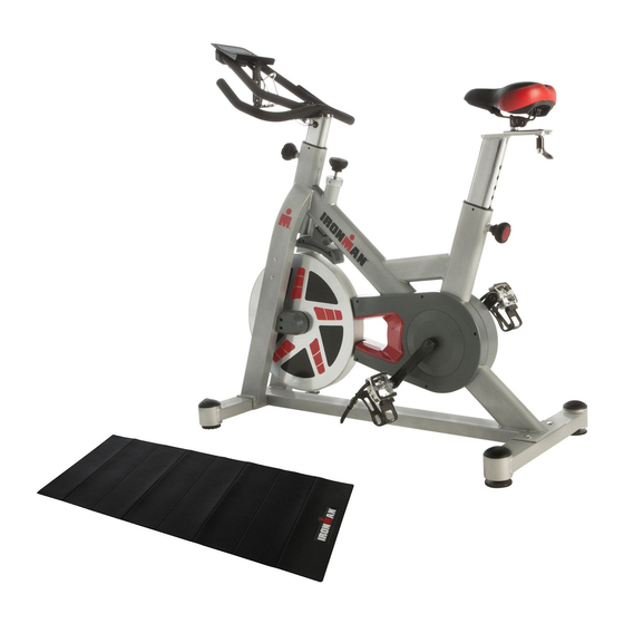
H-Class 520
Magnetic Tension Indoor Training Cycle
6250.6-080916
The specifications of this product may vary from this photo and are subject to change without notice.
IRONMAN, IRONMAN TRIATHLON and M-DOT are registered trademarks of World Triathlon Corporation.
This product is licensed by the World Triathlon Corporation.
Advertisement
Table of Contents

Subscribe to Our Youtube Channel
Related Manuals for Ironman Fitness H-Class 520


Summary of Contents for Ironman Fitness H-Class 520
- Page 1 OWNER’S MANUAL H-Class 520 Magnetic Tension Indoor Training Cycle 6250.6-080916 The specifications of this product may vary from this photo and are subject to change without notice. IRONMAN, IRONMAN TRIATHLON and M-DOT are registered trademarks of World Triathlon Corporation. This product is licensed by the World Triathlon Corporation.
-
Page 3: Table Of Contents
TABLE OF CONTENT SERVICE --------------------------------------------------------------------------- 4 LABEL PLACEMENT ---------------------------------------------------------- 5 PRODUCT SAFETY ----------------------------------------------------------- 6 OVERVIEW DRAWING ------------------------------------------------------- 7 PARTS LIST ---------------------------------------------------------------------- 8 HARDWARE AND TOOL LIST ---------------------------------------------- 9 ASSEMBLY ---------------------------------------------------------------------- 10 HOW TO USE ------------------------------------------------------------------- 16 COMPUTER --------------------------------------------------------------------- 17 HEART RATE CHEST BELT ------------------------------------------------ 19 TROUBLESHOOTING &... -
Page 4: Service
SERVICE IMPORTANT: FOR NORTH AMERICA ONLY For damaged or defective product, questions, replacement parts or any other service support, please contact our customer service department (8:00 AM - 5:00 PM Pacific Standard Time, Daily) by the below methods: For Best Service, please Email: Service@paradigmhw.com Response Time: 1- 2 Business Days Website:... -
Page 5: Label Placement
LABEL PLACEMENT ... -
Page 6: Product Safety
PRODUCT SAFETY Basic precautions should always be followed, including the following safety instructions when using this equipment. Read all instructions before using this equipment. Read all the instructions in this manual and do warm up exercises before using this equipment. Make sure all components are not damaged and in working order before use. This equipment should be placed on a flat surface while in use. -
Page 7: Overview Drawing
OVERVIEW DRAWING ... -
Page 8: Parts List
PART LIST Description Qty No. Description 001 Main Frame 037 Washer 10x19x1.5 002 Front Stabilizer 042 Compressed Spring Ø1.5x9 003 Rear Stabilizer 044 Flange Nut M12x1.5x10.4T 004 Upright Post 40x80x2T 046 Washer 10x29x2T 007 Seat Slide Guide 1 047 Self-Tapping Screw M5x12 009 Seat VL-6100 1 048 Bottle Holder 013 Main Chain Cover-R... -
Page 9: Hardware And Tool List
HARDWARE & TOOL LIST STEP 1 STEP 2 STEP 3 NO.82X2 NO.83X2 NO.90x2 STEP 6 NO.35x4 NO.36X4 NO.37X4 NO.24x1 NO.25x1 NO.46x1 STEP 8 NO.46x1 NO.23x1 NO.22x1 Multi Hex Tool with Open End Wrench 14,17MM 1PC Phillips Screwdriver 1PC 6250 Open End Wrench 13,15MM 1PC... -
Page 10: Assembly
ASSEMBLY Step 1 Place a block of styrofoam underneath the Main Frame (1) for easier installation. Attach the Front Stabilizer (2) to the Main Frame by aligning the bolt holes and installing two Carriage Bolts (36), two Washers (37) and two Cap Nuts (35) as shown below. Tighten the Cap Nuts (35) with the 14,17mm Open End Wrench Provided. - Page 11 ASSEMBLY Step 2 Attach the Computer Holder (80) onto the Handlebars (97) and tighten it using the two Bolts (82) and the Multi Hex Tool with Phillips Screwdriver provided. Insert the batteries into the Computer (81) and insert the Computer (81) into the Computer Holder (80). Ensure that the computer clicks into position.
- Page 12 ASSEMBLY Step 4 Connect the Sensor wire (85) and Sensor connecting wire-2 (86). Turn the Spring Knob (21) on the Main Frame (1) in a counterclockwise direction until it can be pulled out. Pull and hold the Spring Knob (21), insert the Upright Post (4) into the Main Frame (1), and attach the Upper Post Plate (96) onto the Upright Post (4).
-
Page 13: Washer 10X29X2T
ASSEMBLY Step Slide the Handlebar (97) onto the front of the Upright Post (4) and attach it by sliding the Washer (46) onto Knob (23). Then insert the knob through the handlebar bracket hole and the Upright Post (4) slot. Next, slide the Washer (25) and Lock Nut (24) onto the knob and secure by turning the knob clockwise while holding the washer and locknut in place. - Page 14 ASSEMBLY Step 6 Plug the lower end of the Sensor Connecting Wire 2 (86) from the left side of the Front Post (4) to Sensor Wire 1 (87) on the handlebars. Plug the upper end of the Sensor Connecting Wire 1 (87) located at the top portion of the handlebars, into the computer (81).
- Page 15 ASSEMBLY Step 7 Install the Seat Slide Guide (7) onto the Seat Post (5) and tighten with L-Knob (22) and Washer (46). Install the Seat (9) onto the Seat Slide Guide (7) and tighten with the 13,15mm Wrench. Hardware: Tool: 13, 15mm Open End Wrench 1PC (46) Washer 10x29x2T...
-
Page 16: How To Use
HOW TO USE Tension Adjustment Turn knob clockwise to increase tension Turn knob counter-clockwise to decrease tension Emergency Stop Press down the knob to stop the flywheel Foot Strap Put your foot forward as possible into the shoe cage, pull the foot strap snygly around your shoe to avoid slipping off the pedal, see picture. -
Page 17: Computer
COMPUTER BUTTON FUNCTION To select training mode and adjust function value up. DOWN To select training mode and adjust function value down. RESET Total Reset. To reboot the console. MODE Confirm setting or selection. To turn on Bluetooth function DISPLAY FUNCTION TIME Display range 0:00~99:59. - Page 18 COMPUTER OPERATING PROCEDURE 1. POWER ON: The Computer will automatically turn on when you begin exercise. 2. MANUAL PROGRAM Set Target Time, Distance and Calories by MODE button . 3. BLUETOOTH CONNECTION Press to turn on the Bluetooth (BT) function. The BT status light will flash once every 5 seconds when the BT function is on but has not yet connected to a smart device (phone, tablet).
-
Page 19: Heart Rate Chest Belt
HEART RATE CHEST BELT 1. For the most accurate readings, the transmitter belt must have direct contact with the skin. 2. For accurate readings, stay within 4 feet of the computer. 3. The belt will send your pulse to the computer. clockwise. Replace the dead battery with a new CR2032 3V battery. Replace the battery cover and turn clockwise to tighten. 5. You can check battery function without the computer by placing one hand on each sensor... -
Page 20: Troubleshooting & Maintenance
TROUBLE SHOOT & MAINTENANCE TROUBLESHOOTING Computer not working correctly Check to make sure the computer cable is connected securely. The bike wobbles or shakes when in use Turn the adjustable leveler on the front stabilizer or rear stabilizer as needed to level the bike. Squeaking noise when in use The bolts may be loose on the bike. -
Page 21: Warranty
WARRANTY MANUFACTURER’S LIMITED WARRANTY Paradigm Health & Wellness warrants to the original purchaser that this product is free from defects in material and workmanship when used for the purpose intended, under the conditions that it has been installed and operated in accordance with Paradigm’s Owner’s Manual. Paradigm’s obligation under this warranty applies to the following: COMPONENT... -
Page 22: Parts Request Form
PARTS REQUEST FORM Paradigm Health & Wellness, Inc EMAIL THIS FORM WITH YOUR RECEIPT OF PURCHASE TO Service@paradigmhw.com * NAME: ADDRESS: CITY STATE TELEPHONE: (Day) (Night) SERIAL#: MODEL#: PURCHASE DATE: PLACE OF PURCHASE: PART # DESCRIPTION “YOUR ORDER WILL BE PROCESSED WITHIN 3 BUSINESS DAYS” *This form can also be faxed to #: 626-810-2166...
Need help?
Do you have a question about the H-Class 520 and is the answer not in the manual?
Questions and answers