Table of Contents
Advertisement
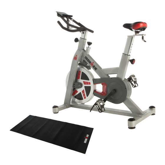
OWNER'S MANUAL
H-Class 520
Magnetic Tension Indoor Training Cycle
Model 6250
The specifications of this product may vary from this photo and are subject to change without notice.
IRONMAN, IRONMAN TRIATHLON and M-DOT are registered trademarks of World Triathlon Corporation.
This product is licensed by the World Triathlon Corporation.
1
Advertisement
Table of Contents

Subscribe to Our Youtube Channel
Related Manuals for Ironman Fitness H-Class 520


Summary of Contents for Ironman Fitness H-Class 520
- Page 1 OWNER’S MANUAL H-Class 520 Magnetic Tension Indoor Training Cycle Model 6250 The specifications of this product may vary from this photo and are subject to change without notice. IRONMAN, IRONMAN TRIATHLON and M-DOT are registered trademarks of World Triathlon Corporation.
- Page 2 6250.1-082814...
-
Page 3: Table Of Contents
TABLE OF CONTENT SERVICE ------------------------------------------------------------------------ 4 LABEL PLACEMENT --------------------------------------------------------- 5 PRODUCT SAFETY ---------------------------------------------------------- 6 OVERVIEW DRAWING ------------------------------------------------------ 7 PARTS LIST -------------------------------------------------------------------- 8 HARDWARE AND TOOL LIST --------------------------------------------- 10 ASSEMBLY --------------------------------------------------------------------- 11 - - - - - - - - - - - - - - - - - -... -
Page 4: Service
SERVICE IMPORTANT: FOR NORTH AMERICA ONLY To request product service and order replacement parts, please call our customer service department at: 1-844-641-7922 Monday through Friday, 8:00 AM-5:00 PM Pacific Standard Time, service@paradigmhw.com or email us at: Please visit our website at www.paradigmhw.com. Please have the following information ready when requesting for service: Your name Phone number... -
Page 5: Label Placement
LABEL PLACEMENT... -
Page 6: Product Safety
PRODUCT SAFETY Basic precautions should always be followed, including the following safety instructions when using this equipment. Read all instructions before using this equipment. Read all the instructions in this manual and do warm up exercises before using this equipment. Before exercising and to avoid injuring your muscles, perform warm-up exercise for each muscle group is highly recommended. -
Page 7: Overview Drawing
OVERVIEW DRAWING... -
Page 8: Parts List
PA RTS LIST Description Qty No. Description 001 Main Frame 025 Washer 19.5x38x2T Front stabilizer bar 026 Magnet plastic cover 40x80x2T Rear stabilizer bar 027 Support bar 20x20x1.4T 40x80x2T 004 Upright post 40x80x2T 028 Magnet bracket 005 Seat post 40x80x2T 029 Tension control bar 006 Handlebar Φ25.4x2T 030 Fixed cover... - Page 9 PARTS LIST Description Qty No. Description Plastic sleeve 051 Washer 20.5x25x1T Φ7.9x12.7x23.5mm 052 Self-tapping screw M4.5x15 073 Fixed plate 053 Self-tapping screw M4.2x10 17 074 Cushion knob M10x25 054 Hex. Bolt M6x35 075 Cap Φ76 055 Idle wheel fixture 076 Transport wheel Φ70 056 Nylon nut M10x6T 077 Tension control knob M10 057 Steel sleeve Φ25.1x32x10T...
-
Page 10: Hardware And Tool List
HARDWARE & TOOL LIST NO.23 Knob NO. 25 Washer NO. 35Cap nut NO. 37 Washer M10x28 1PCS 19.5x38x2T 1PCS M10 4PCS 10x19x1.5T 4 PCS NO. 24 Lock Nut NO. 46 Washer NO. 82 Bolt NO. 83 Bolt M5x12 M10 1PCS 10x29x2T 2PCS M6x10 2PCS 2PCS... -
Page 11: Assembly
ep 1 sition the F Front Stabil lizer (2) in front of the e Main Fra ame (1) and d align bol hole es. Attach h the Front t Stabilizer r (2) onto th he front bracket of Main Fram me (1) with h two Carri... - Page 12 Step 2 Insert Computer (81) into the Computer Holder (80), and attach the Computer Holder (80) onto the Handlebar (6) then tighten with two Bolts (82). Ensure the console clicks into position Tool: Hardware: NO. 82 Bolt Multi Hex Tool with Phillips M6x10 2PC Screwdriver 1PCS ep 3...
- Page 13 Step 4 Connect the Sensor wire (85) and Sensor connecting wire-2 (86). Turn the Spring Knob (21) on the Main Frame (1) in a counterclockwise direction until it can be pulled out. Pull and hold the Spring Knob, insert the Upright Post (4) into Main Frame (7).
- Page 14 Step 6 Install the Seat Slide Guide (7) onto the Seat Post (5) and tighten with L-Knob (22) and Washer (46). Install the Seat (9) onto the Seat Slide Guide (7) and tighten with the Wrench. Tool: Hardwa Open End Wrench 13,15MM 1PCS NO.
-
Page 15: How To Use
HOW TO USE Tension Adjustment Turn knob clockwise to increase tension Turn knob counter-clockwise to decrease tension Emergency Stop Press down the knob to stop the flywheel Foot Strap Put your foot forward as possible into the shoe cage, pull the foot strap snygly around your shoe to avoid slipping off the pedal, see picture. -
Page 16: Computer
COMPUTER BUTTON FUNCTION To select training mode and adjust function value up. DOWN To select training mode and adjust function value down. RESET Total Reset. To reboot the console. MODE Confirm setting or selection. To turn on Bluetooth function DISPLAY FUNCTION TIME Display range 0:00~99:59. - Page 17 COMPUTER 2. MANUAL PROGRAM Set Target Time, Distance and Calories by MODE button . 3. BLUETOOTH CONNECTION Press to turn on the Bluetooth (BT) function. BT status light will flash once every 5 seconds when the BT function is on but has not yet connected to a smart device (phone, tablet).
-
Page 18: Heart Rate Chest Belt
HEART RATE CHEST BELT 1. For the most accurate readings, the transmitter belt must have direct contact with the skin. 2. For accurate readings, stay within 4 feet of the computer. 3. The belt will send your pulse to the computer. clockwise. -
Page 19: Warm Up
WARM UP Quadriceps Stretch With one hand against a wall for balance, reach behind you and pull your right foot up. Bring your heel as close to your buttocks as possible. Hold for 15 counts and repeat with left foot up. Inner Thigh Stretch Sit with the soles of your feet together with your knees pointing outward. -
Page 20: Troubleshooting & Maintenance
TROUBLE SHOOT & MAINTENANCE TROUBLESHOOTING Computer not working correctly Check to make sure the computer cable is connected securely. The bike trainer wobbles or shakes when in use Turn the adjustable leveler on the front stabilizer or rear stabilizer as needed to level the bike trainer. -
Page 21: Warranty
WARRANTY MANUFACTURER’S LIMITED WARRANTY Paradigm Health & Wellness warrants to the original purchaser that this product is free fromdefects in material and workmanship when used for the purpose intended, under the conditions that it has been installed and operated in accordance with Paradigm’s Owner’s Manual. Paradigm’s obligation under this warranty applies to the following: COMPONENT LENGTH OF WARRANTY... -
Page 22: Fax Form
Paradigm Health & Wellness, Inc. PARTS REQUEST FAX FORM Please fax this form to (1-626-810-2166) OR YOU CAN EMAIL CUSTOMER SERVICE REQUESTS TO service@paradigmhw.com NAME: _______________________________________________________ ADDRESS: ____________________________________________________ CITY ______________ STATE ______________ ZIP ___________________ TELEPHONE: (Day) _____________________________________________ (Night) ____________________________________________ (Email Address) ____________________________________ SERIAL#: __________________________________________ MODEL#: __________________________________________ PURCHASE DATE: ______________________________________________...
Need help?
Do you have a question about the H-Class 520 and is the answer not in the manual?
Questions and answers