Table of Contents
Advertisement
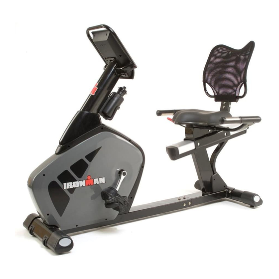
Owner's Manual
Odyssey Recumbent Bike
Customer Service
(800) 750-4766
Manufactured By:
Ironman Fitness
4009 Distribution Drive
Suite 250
Garland, TX 75041
CAUTION
Read all precautions and instructions in
this manual before using this equipment.
Model Name : ODYSSEY
Serial Number :
Serial Number can be found at
the above specified location.
315-00135
09/18 Rev 7.0
Advertisement
Table of Contents

Related Manuals for Ironman Fitness Recumbent Bike ODYSSEY


Summary of Contents for Ironman Fitness Recumbent Bike ODYSSEY
- Page 1 Owner’s Manual Odyssey Recumbent Bike Customer Service (800) 750-4766 Manufactured By: Ironman Fitness 4009 Distribution Drive Suite 250 Garland, TX 75041 CAUTION Read all precautions and instructions in this manual before using this equipment. Model Name : ODYSSEY Serial Number : Serial Number can be found at the above specified location.
-
Page 2: Table Of Contents
This manual will guide you through the assembly process. If at any time you are having trouble with the assembly or use of this product, then please contact us at our Ironman Fitness Help line. We have trained service technicians on site to take care of you, our valued customer. -
Page 3: Important Safety Information
The unit should only be used on a level surface and is intended for indoor use only. The unit should not be placed in a garage, patio, or near water and should never be used while you are wet. Ironman Fitness recommends a mat be placed under the unit to protect floor or carpet and for easier cleaning. -
Page 4: Assembly
Assembly www.ironmanfitness.com... -
Page 5: Parts Identifier
Front Frame Rear Frame Console Upright Post Set Screw M6x8 Seat Sup- Water Bottle port Frame Holder Prior to assembly, remove components from the box and verify that all the listed parts were supplied. Right Handlebar Upright Handlebar Allen Screws M8x15 Front Stabilizer... -
Page 6: Assembly Steps
www.ironmanfitness.com ASSEMBLY FOR REAR STABILIZER Secure the rear stabilizer (D) to the rear main frame (B) using 2 allen screws (N7), 2 spring washers (N2) and 2 flat washers (N3). Note: Front stabilizer (C) is very similar to rear stabilizer (D) but contains transport wheels. Make sure not to get them mixed up. - Page 7 ASSEMBLY FOR FRONT STABILIZER Secure the front stabilizer (C) to the main frame (A) using 2 allen screws (N7), 2 spring washers (N2) and 2 flat washers (N3) ASSEMBLY FOR FRONT & REAR MAIN FRAME Step 1: Connect the front (A10) and rear (B20) pulse wires together.
- Page 8 www.ironmanfitness.com ASSEMBLY FOR UPRIGHT POST Step 1: Insert the upright post cover (N9) to the upright post (e) from the bottom side. Step 2: Connect the lower pulse wire (A10) with the upper pulse wire (e2). Also, connect the lower sensor wire (A8) with the upper sensor wire (e3).
- Page 9 ASSEMBLY FOR UPRIGHT HANDLEBAR Attach the handlebar (F) to the upright post (e) and secure it with 2 allen screws (N5) and 2 flat washers (N11). L-(L) L-Left COUNTER- CLOCKWISE Use Tool 15mm L-(R) Use Tool L-Right CLOCKWISE www.ironmanfitness.com ASSEMBLY FOR PEDALS Step 1: Attach left pedal strap (l1) to left pedal (l- l) and right pedal strap (l2) to right (l-R)
- Page 10 www.ironmanfitness.com Step 1: Connect the sensor wire (e3) and the pulse wire (e2) with the corresponding wires on the console (G). Step 2: Remove 2 screws (G2) from the back of the console (G). Step 3: Gently push all wires into the upright post and attach the console to the console mounting plate at the top of the upright tube (e).
- Page 11 www.ironmanfitness.com ASSEMBLY FOR SEAT SLIDE ADJUSTMENT Insert the seat slide adjustment handle (N10) into the seat slide adjustment collar on the seat slide assembly (B9). Secure it with M6x8 set screw (N4). Use Tool ASSEMBLY FOR SIDE HANDLEBARS Step 1: Use Tool Starting with left handlebar (H1), Connect pulse wire (H14) and pulse wire (B20).
- Page 12 Use Tool www.ironmanfitness.com ASSEMBLY FOR SEAT SUPPORT FRAME Attach the seat support frame (J) to the seat slide assembly (B9) and secure it using 3 screws (N6) and 3 flat washers (N3). Assembly...
- Page 13 Use Tool www.ironmanfitness.com ASSEMBLY FOR SEAT CUSHION Attach seat (K2) to the seat support frame (J) using 4 allen screws (N1) and 4 flat washers (N3). Important Information Assembly...
- Page 14 Use Tool www.ironmanfitness.com ASSEMBLY FOR BACK REST Attach the back rest (K1) to the seat support frame (J) and secure it using 4 allen screws (N1), 4 spring washers (N2) and 4 flat washers (N3). Important Information Assembly...
- Page 15 www.ironmanfitness.com Congratulations! You have completed the assembly of your new Ironman Odyssey Recumbent Bike! Assembly...
- Page 16 www.ironmanfitness.com AC ADAPTER PLUG-IN LOCATION ADJUSTING YOUR SEAT PULL UP (LOCK) PULL DOWN (RELEASE) TRANSPORTING YOUR UNIT TRANSPORT WHEELS Important Information Assembly...
-
Page 17: Console Information
www.ironmanfitness.com Console Information www.ironmanfitness.com Important Information... -
Page 18: Console Buttons
www.ironmanfitness.com CONSOLE BUTTONS: UP/DOWN: These buttons are used to change programs and set- tings. ENTER: This button is used as an entry key, which will allow user to confirm settings such as time, distance and calories. RECOVERY: This button is used to begin the Recovery feature of the console (refer to Console Function section for more information). -
Page 19: Console Functions
www.ironmanfitness.com CONSOLE FUNCTIONS: TIME: If a target time was not selected, time will count up from 00:00 to maximum 99:59. When working out with a target time, time will count down from target to 00:00. When selecting target time, use the ▲ / ▼ buttons, the time will change in 1 minute increments and can range from 1:00 min to 99:00 mins. -
Page 20: General Information
www.ironmanfitness.com RECOVERY: After your workout, press “ReCOVeRY” button and quickly grab pulse plates. All func- tion display will stop except “TIMe” starts counting down from 00:60 to 00:00. Screen will display your heart rate recovery status rating between F1-F6. F1 is the best, F6 is the worst. -
Page 21: Preset Programs
PRESET PROGRAMS: each Program is divided into twenty segments. Use the UP/DOWN buttons to scroll to this program. Use the UP/DOWN buttons to select desired preset (P01-P12). Press eNTeR to confirm. Press MODe/eNTeR to select this program. The resistance level l01 will flash. Use the Up (▲) or Down (▼) button to select your desired resistance. -
Page 22: Monitoring Your Heart Rate
www.ironmanfitness.com MONITORING YOUR HEART RATE: To obtain the greatest cardiovascular benefits from your exercise workout, it is important to work within your target heart rate zone. The American Heart Association (AHA) defines this target as 60%-75% percent of your maximum heart rate. Your maximum heart rate may be roughly calculated by subtracting your age from 220. -
Page 23: Target Heart Rate Zone
Fitness Safety - The Heart Rate chart indicates aver- age rate for you. Your physician or health care profes- sional can help you determine the exercise intensity that is appropriate for your age and condition. www.ironmanfitness.com TARGET HEART RATE ZONE 100% Serious athletic... -
Page 24: Workout Information
Workout Information www.ironmanfitness.com Important Information... - Page 25 Prone on Elbows Lie on your stomach with your feet together. Rest on your forearms with your elbows directly under your sholdres. Relax lower back and abdomen into the floor. Hold for 30-60 seconds or until muscles feel looser Cat and Camel Rest on your hands and knees.
- Page 26 www.ironmanfitness.com Wrist Extensor Extend your right arm in front of you with your palm up and your elbow straight. Point your fingertips toward the floor by bending at the wrist. Using your left hand, pull the back of your right hand toward you gently.
- Page 27 Calf Stretch Face a solid structure such as a wall with your left foot ahead of your right, toes straight ahead. Bend your left knee, press your hips forward, and lean into the wall. Keep both heels down, your right leg straight, and you left knee over your ankle.
-
Page 28: Parts Information
Parts Information www.ironmanfitness.com Important Information... - Page 29 www.ironmanfitness.com Exploded View Important Information...
-
Page 30: Parts List
www.ironmanfitness.com Important Information Parts List Odyssey Parts List Rev A Ref # Description MAIN FRAME A2-1 DRIVING WHEEL A2-2 AXLE A2-3 A2-4 SCREW A2-5 BEARING A2-6 C CLIP A2-7 MAGNET FLYWHEEL A3-1 C-CLIP, C10 A3-2 BEARING 6203ZZ A3-4 NUT, 3/8"X0.5 A3-5 AXLE A3-6... -
Page 31: Warranty
Missing/Cosmetic Parts: 30 Days Limited Warranty This Limited Warranty applies in the United States and Canada to Products manufactured or distributed by IRONMAN Fitness under the IRONMAN Fitness (“IRONMAN”) brand name (as used herein, the “Product” or “Products”). The warranty period to the original purchaser is listed above, and commences on the date of original purchase of the product, unless otherwise autho- rized by IRONMAN. - Page 32 Ironman Fitness 4009 Distribution Drive, Suite 250 Garland, Texas 75041 Customer Service: 1-800-750-4766 IRONMAN, IRONMAN TRIATHLON and M-DOT are registered trademarks of World Triathlon Corporation. This product is licensed by the IRONMAN TRIATHLON. Important Information...
Need help?
Do you have a question about the Recumbent Bike ODYSSEY and is the answer not in the manual?
Questions and answers