Table of Contents
Advertisement
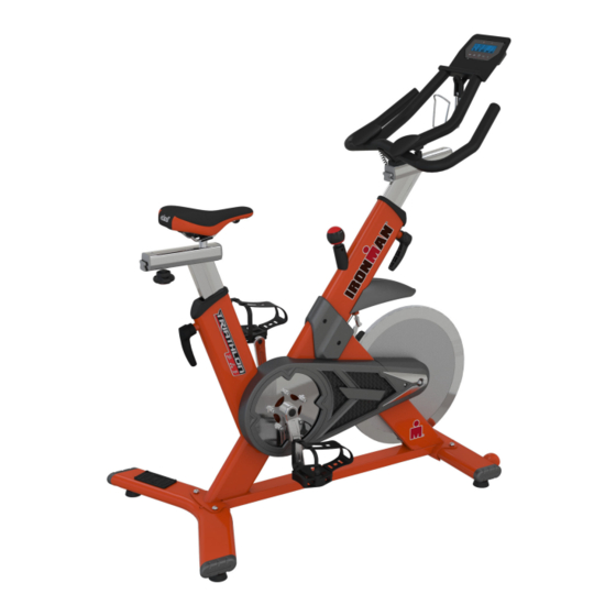
Triathlon X-Class 510
Exercise Bike
Model 6252
The specifications of this product may vary from this photo and are subject to change without notice.
IRONMAN, IRONMAN TRIATHLON and M-DOT are registered trademarks of World Triathlon Corporation.
This product is licensed by the World Triathlon Corporation.
1
Advertisement
Table of Contents

Related Manuals for Ironman Fitness Triathlon X-Class 510


Summary of Contents for Ironman Fitness Triathlon X-Class 510
- Page 1 Triathlon X-Class 510 Exercise Bike Model 6252 The specifications of this product may vary from this photo and are subject to change without notice. IRONMAN, IRONMAN TRIATHLON and M-DOT are registered trademarks of World Triathlon Corporation. This product is licensed by the World Triathlon Corporation.
- Page 2 6252.1-112714...
-
Page 3: Table Of Contents
TABLE OF CONTENT SERVICE ------------------------------------------------------------------------ 4 LABEL PLACEMENT --------------------------------------------------------- 5 PRODUCT SAFETY ---------------------------------------------------------- 6 OVERVIEW DRAWING ------------------------------------------------------ 7 HARDWARE AND TOOLS LIST ------------------------------------------- 9 PART LIST ---------------------------------------------------------------------- 10 ASSEMBLY --------------------------------------------------------------------- 12 HOW TO USE ---------------------------------- ------------------------------- 19 COMPUTER -------------------------------------------------------------------- 21 HEART RATE CHEST BELT ---------------------------------------------- 23 WARM UP ----------------------------------------------------------------------- 24 TROUBLESHOOTING &... -
Page 4: Service
SERVICE IMPORTANT: FOR NORTH AMERICA ONLY To request product service and order replacement parts, please call our customer service department at: 1-844-641-7922 Monday through Friday, 8:00 AM-5:00 PM Pacific Standard Time, service@paradigmhw.com or email us at: Please visit our website at www.paradigmhw.com. Please have the following information ready when requesting for service: Your name Phone number... -
Page 5: Label Placement
LABEL PLACEMENT... -
Page 6: Product Safety
PRODUCT SAFETY Basic precautions should always be followed, including the following safety instructions when using this equipment. Read all instructions before using this equipment. Read all the instructions in this manual and do warm up exercises before using this equipment. Before exercising and to avoid injuring your muscles, perform warm-up exercise for each muscle group is highly recommended. -
Page 7: Overview Drawing
OVERVIEW DRAWING... - Page 8 OVERVIEW DRAWING...
-
Page 9: Hardware And Tools List
HARDWARE & TOOL LIST (#29) Hex Screw (#3) HEXAGONAL BOLT (#4) Washer ˜10× 20×t2.0(mm) M6x8mm 1PC M10×L:55(mm) 4PCS 4PCS (#104) Allen Wrench (#105)Allen Wrench (#103)Allen Wrench 4mm 1PC 5mm 1PC (#106) Allen Wrench with (#102) Wrench Tool (#107)Thread Sealant Screwdriver 6mm 13,14,15,17mm 1PC... -
Page 10: Part List
PARTS LIST Description Description 001 PEDAL(L) 032 HEXAGONAL NUT M8×7(mm) 033 LOWER BRAKE AXLE 002 PEDAL(R) 034 BRAKE BALANCE BAR 003 HEXAGONAL BOLT M10×L:55(mm) 035 BRAKE PAD 004 WASHER ˜10× 20×t2.0(mm) 036 BRAKE BALANCE BUSHING 005 Seat Cushion 037 SPRING 37×20× ˜ 1.5(mm) 007 MAIN FRAME SET 008 BEARING-6004ZZ 038 SPRING ˜15×... -
Page 11: Parts List
PARTS LIST No. Description No. Description 062 RUBBER PAD 085 HEXAGONAL SCREW M5×10(mm) 063 BOLT 086 FLYWHEEL 064 WASHER 087 AXLE SLEEVE 065 BOLT 088 WASHER ˜27× ˜ 20.5×t:3(mm) 066 CONSOLE PLATE 089 CHAIN COVER 067 CONSOLE 090 DART-SHAPED COVER 091 SELF-TAPPING SCREW 068 BOTTLE HOLDER M3×8(mm) -
Page 12: Assembly
ASSEMBLY (#106) Allen Wrench with Screwdriver 6mm Step 1 Attach Front Stabilizer Set (#76) to frame with two Washers (#4) and two Hexagonal Bolt (#3) and then tighten firmly by using Allen Wrench with Screwdriver 6mm (#106) (#106) Allen Wrench with Screwdriver 6mm Step 2 Attach Rear Stabilizer Set (#82) to frame with two Washers (#4) and two Hex... - Page 13 ASSEMBLY (#107)Thread Sealant Step 3 Fully coat entire threads with Thread Sealant (#107) on the thread of the Left and Right Pedal (#1/ #2) before pedal assembly. Before applying thread sealant, make sure parts are clean. Allow sealant to dry for 12 hours to fully cure before use.
- Page 14 ASSEMBLY Left Right (#102) Wrench Tool 13,14,15,17mm 1PC Step 4 The Cranks and Pedals are marked “R” for Right and “L” for Left. Left Pedal: Insert Left Pedal (#1) into threaded hole in the Left Crank (#12). Using your hand, turn the pedal shaft counter-clockwise direction until snug. Use the wrench, tighten the pedal shaft counter-clockwise Right Pedal: Repeat steps above but in clockwise direction...
- Page 15 ASSEMBLY Tool (#106) Allen Wrench with Screwdriver 6mm Step 5 Insert 4 AA batteries (included) into the back of the Console (67). Attach the Console (67) to the Console Plate (66), and then tighten Console Plate (66) to Handlebar Set (54) with two Bolts (65). Note: Console should "click" into place. Tool (#104) Allen Wrench 4mm 1PC...
- Page 16 ASSEMBLY Tool (#105)Allen Wrench 5mm 1PC Step 7 Slide the Handlebar Set (54) onto the Handlebar Adjustable Post (70) in the direction shown above. Note: Hex Screw and Upper Slider End Caps were packaged with this manual. Install the Hex Screw (#29) from underneath the Handlebar as shown on the left.
- Page 17 ASSEMBLY #100 Step 8 Insert the Sensor Wire (#100) into the Console (#67). #100 #101 Step 9 Connect Sensor Wire (#100) with Speed Sensor Wire (#101)
- Page 18 ASSEMBLY (#102) Wrench Tool 13,14,15,17mm 1PC Step 10 Insert Seat Cushion (#5) into Seat Slider (#73) and tighten firmly by using Wrench Tool (#102). Step 11 The Bike should be on a level surface. Turn the Rubber Knob (#46) to raise or lower to, make sure all Rubber Knobs touch the floor.
-
Page 19: How To Use
HOW TO USE Seat height adjustment Turn Fixed Handle (#27) counter-clockwise to unlock. Slide the seat up or down to desire position. Turn Fixed Handle clockwise to lock. Do not raise the seat post over the STOP line Seat slide adjustment Turn Adjustable Knob (#53) counter-clockwise to unlock. -
Page 20: Foot Strap
HOW TO USE Tension Adjustment Turn knob clockwise to increase tension Turn knob counter-clockwise to decrease tension Emergency Stop Press down the knob to stop the flywheel Foot Strap Put your foot forward as possible into the shoe cage, pull the foot strap snygly around your shoe to avoid slipping off the pedal, see picture. -
Page 21: Computer
COMPUTER BUTTON FUNCTION To select training mode and adjust function value up. DOWN To select training mode and adjust function value down. RESET Total Reset. To reboot the console. MODE Confirm setting or selection. To turn on Bluetooth function DISPLAY FUNCTION TIME Display range 0:00~99:59. - Page 22 COMPUTER 2. MANUAL PROGRAM Set Target Time, Distance and Calories by MODE button. 3. BLUETOOTH CONNECTION Press to turn on the Bluetooth (BT) function. BT status light will flash once every 5 seconds when the BT function is on but has not yet connected to a smart device (phone, tablet).
-
Page 23: Heart Rate Chest Belt
HEART RATE CHEST BELT 1. For the most accurate readings, the transmitter belt must have direct contact with the skin. 2. For accurate readings, stay within 4 feet of the computer. 3. The belt will send your pulse to the computer. 4. -
Page 24: Warm Up
WARM UP Quadriceps Stretch With one hand against a wall for balance, reach behind you and pull your right foot up. Bring your heel as close to your buttocks as possible. Hold for 15 counts and repeat with left foot up. Inner Thigh Stretch Sit with the soles of your feet together with your knees pointing outward. -
Page 25: Troubleshooting & Maintenance
TROUBLE SHOOT & MAINTENANCE TROUBLESHOOTING Computer not working correctly Check to make sure the computer cable is connected securely. The bike trainer wobbles or shakes when in use Turn the adjustable leveler on the front stabilizer or rear stabilizer as needed to level the bike trainer. -
Page 26: Warranty
WARRANTY MANUFACTURER’S LIMITED WARRANTY Paradigm Health & Wellness warrants to the original purchaser that this product is free fromdefects in material and workmanship when used for the purpose intended, under the conditions that it has been installed and operated in accordance with Paradigm’s Owner’s Manual. Paradigm’s obligation under this warranty applies to the following: COMPONENT LENGTH OF WARRANTY... -
Page 27: Fax Form
Paradigm Health & Wellness, Inc. PARTS REQUEST FAX FORM Please fax this form to (1-626-810-2166) OR YOU CAN EMAIL CUSTOMER SERVICE REQUESTS TO service@paradigmhw.com NAME: _______________________________________________________ ADDRESS: ____________________________________________________ CITY ______________ STATE ______________ ZIP ___________________ TELEPHONE: (Day) _____________________________________________ (Night) ____________________________________________ (Email Address) ____________________________________ SERIAL#: __________________________________________ MODEL#: __________________________________________ PURCHASE DATE: ______________________________________________...
Need help?
Do you have a question about the Triathlon X-Class 510 and is the answer not in the manual?
Questions and answers