REMEHA P 420 Installation And Service Manual
Fuel oil/gas boilers
Hide thumbs
Also See for P 420:
- Assembly instructions manual (24 pages) ,
- Technical instructions (24 pages)
Table of Contents
Advertisement
Advertisement
Table of Contents

Related Manuals for REMEHA P 420


Summary of Contents for REMEHA P 420
- Page 1 Remeha Fuel oil/gas boilers P 420 Installation and Service Manual 300016839-03...
-
Page 2: Declaration Of Conformity
The appliance complies with the standard model described in declaration of compliance . It is manufactured and distributed pursuant to the requirements of european directives. The original declaration of conformity is available from the manufacturer. P 420 16/03/2016 - 300016839-03... -
Page 3: Table Of Contents
Spare parts................22 16/03/2016 - 300016839-03 P 420... -
Page 4: Safety Instructions
Depending on the settings of the appliance: - The temperature of the radiators may reach 95°C - The temperature of the domestic hot water may reach - The temperature of the flue gas conduits may exceed 65°C 60°C P 420 16/03/2016 - 300016839-03... -
Page 5: Recommendations
- Explain the installation to the user - If a maintenance is necessary, warn the user of the obligation to check the appliance and maintain it in good working order - Give all the instruction manuals to the user 16/03/2016 - 300016839-03 P 420... -
Page 6: About This Manual
The boilers and hot water tanks are designed and manufactured in accordance with the sound engineering practice, as requested in article 3.3 of the directive 97/23/EC, it is certified by compliance with the directives 90/396/EC, 92/42/EC, 2006/95/EC and 2004/108/EC. P 420 16/03/2016 - 300016839-03... -
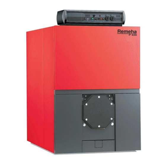
Page 7: Technical Description
The useful power of P 420 boilers is between 250 and 700 kW. Boiler with control panel, which may be fitted with an optional Rematic 2945 C3 control unit for heating only or heating and domestic hot water production. -
Page 8: Installation
(a) Boiler flow - weld (c) Boiler return - weld (b) Sludge removal hole Ø Rp 2 1/2 - plugged (d) Rp 2 draining outlet - plugged Boiler type P 420-8 P 420-9 P 420-10 P 420-11 P 420-12 P 420-13 P 420-14 ø... -
Page 9: Position Of The Boiler
4.3.2 Position of the boiler For the assembly and because of their design, P 420 boilers require If the boiler location is not determined precisely, leave enough space no special base. Their closed furnace system means that the floor around the boiler to facilitate monitoring and maintenance need not have refractory properties. - Page 10 (risk of refrigerant leakage), etc. • Do not stock such products close to the boilers. If the boiler and/or peripheral equipment are corroded by such chloride or fluoride compounds, the contractual guarantee cannot be applied. P 420 16/03/2016 - 300016839-03...
-
Page 11: Example Of An Installation
Sludge decanting pot (particularly recommended on older Independent domestic hot water tanks installations) Domestic hot water loop pump (optional) Flush valve Domestic hot water circulation loop return Water low safety pressure-sensitive switch Domestic hot water outlet Shunt pump Expansion vessel 16/03/2016 - 300016839-03 P 420... -
Page 12: Hydraulic Connections
40°C); The first stage must be set to a minimum of 50% of the nominal stage. Operation with modulating burner - The water temperature in the boiler is maintained at 50°C or more: The burner can modulate down to 30% of the nominal stage. P 420 16/03/2016 - 300016839-03... -
Page 13: Safety Valve
Maximum boiler nominal output is 500 kW. Minimum relieving capacity Minimum safety valve flowrate must be 4000 Kg/h Maximum gross boiler output 4.5.5 Connection of the water circuit for domestic use See: Domestic hot water calorifier instructions. 16/03/2016 - 300016839-03 P 420... -
Page 14: Chimney Connection
Flue size Refer to applicable regulations while determining the size of the flue. Please note that P 420 boilers have pressurised and tight furnaces and that the pressure at the connection to the chimney must not exceed 0 mbar, unless special sealing precautions have been taken, for instance in order to connect a static condenser/regenerator. -
Page 15: Fuel-Oil Or Gas Connections
Do not add cold water suddenly into the boiler when it is make sure that the filled system is free of air before the hot. burner is turned on. 16/03/2016 - 300016839-03 P 420... -
Page 16: Commissioning
6.2 Precautions required if the heating is stopped when there is a risk of freezing We recommend the use of a correctly dosed antifreeze agent to prevent to the heating circuit from freezing. If this cannot be done, drain the system completely. P 420 16/03/2016 - 300016839-03... -
Page 17: Checking And Maintenance
The rating plate fixed on the side of the boiler during installation is used to identify the boiler correctly and also provides the main specifications of the boiler. Boiler type Nominal output Nominal input M000048-B 16/03/2016 - 300016839-03 P 420... -
Page 18: Maintenance
- Unscrew the 4 closing nuts and open the furnace door. - Brush out the inside of the furnace. - Use a vacuum cleaner to remove any soot which has accumulated in the combustion chamber. - Close the door and replace the front panel. C003593-A P 420 16/03/2016 - 300016839-03... -
Page 19: Positioning Of The Baffle Plates
Follow the order of assembly shown in the diagram. The 8-figure part number of the baffle plate is cast in the metal. Boiler P 420-8 P 420-9 - P 420-10 P 420-11 P 420-12 P 420-13 - P 420-14 Upper flue ways... -
Page 20: Chemical Sweeping
- 5 l spray with separate reservoir, nozzle and connecting tube. The nozzles enable easy application at the back of the combustion chamber. Manual pressurisation of the reservoir. - Motor-assisted pressurisation spray with reservoir, nozzle and connecting tube. These sprays are intended for intensive use. P 420 16/03/2016 - 300016839-03... -
Page 21: Cleaning The Casing Material
7.4 Cleaning the casing material Use a soapy solution and a sponge only. Rinse with clean water and dry with chamois leather or a soft cloth. 7.5 Maintenance of the burner Refer to the instructions supplied with the burner. 16/03/2016 - 300016839-03 P 420... -
Page 22: Spare Parts
8 Spare parts To order a spare part, quote the reference number next to the part required. Boiler body P 420 16/03/2016 - 300016839-03... - Page 23 Casing 16/03/2016 - 300016839-03 P 420...
- Page 24 Insulating material for body RC 6 control panel P 420 16/03/2016 - 300016839-03...
- Page 25 17.1 9536-5613 Contact spring for sensor tube Flow switch 8229-8911 Complete combustion chamber door, no opening 8802-4703 Flow controller P 420-7 Complete 10 mm combustion chamber door with 8229-8943 8802-4707 Flow controller P 420-8 opening on request 8802-4710 Flow controller P 420-9...
- Page 26 Brush 8229-0514 Complete rear cover, width 490 mm 9750-5060 1300 mm brush rod 8229-8818 Complete cable way, left, P 420-7 9750-5048 Extension for brush rod 650 mm 8229-8819 Complete cable way, left, P 420-8 9434-5102 Retouching spray paint - anthracite grey...
- Page 27 16/03/2016 - 300016839-03 P 420...
- Page 28 Remeha Commercial UK Part of the BDR THERMEA Remeha House Molly Millars Lane RQ41 2QP Wokingham, Berks After Sales Tel: 01189743076 Technical Enquires: 01189743067 Internet: www.remeha.co.uk © Copyright All technical and technological information contained in these technical instructions, as well as any drawings and technical descriptions supplied, remain our property and shall not be multiplied without our prior consent in writing.
Need help?
Do you have a question about the P 420 and is the answer not in the manual?
Questions and answers