
Related Manuals for REMEHA P 320


Summary of Contents for REMEHA P 320
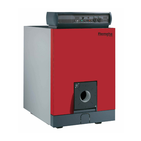
- Page 1 Remeha Fuel oil/gas boilers P 320 Installation and Service Manual 300016243-001-D 63184...
-
Page 2: Declaration Of Conformity
The appliance complies with the standard model described in declaration of compliance . It is manufactured and distributed pursuant to the requirements of european directives. The original of the declaration of compliance is available from the manufacturer. P 320 20/09/2011 - 300016243-001-D... -
Page 3: Table Of Contents
13 Spare parts................19 20/09/2011 - 300016243-001-D P 320... -
Page 4: General
Risk of injury and damage to equipment. Attention must be paid to the Caution danger warnings on safety of persons and equipment Specific information Information must be kept in mind to maintain comfort Reference Refer to another manual or other pages in this instruction manual P 320 20/09/2011 - 300016243-001-D... -
Page 5: Description
The useful power of P 320 boilers is between 55 and 280 kW. Models available Boiler with control panel, which may be fitted with an optional Rematic 2945 C3K control unit for heating only or heating and domestic hot water production. -
Page 6: Technical Specifications
2.1 Technical specifications Maximum operating pressure: 6 bar Safety thermostat setting: 110 °C Boiler thermostat setting: 30 to 90°C Boiler P 320-4 P 320-5 P 320-6 P 320-7 P 320-8 P 320-9 Useful output 70-105 105-140 140-180 180-230 230-280 280-330... -
Page 7: Main Dimensions
(d) 2 1/2 heating return (flange + counter flange) (b) 2 1/2 heating outlet (flange + counter flange) (e) Rp 1 1/2 draining outlet (supplied with plug) (c) Sludge removal hole Ø Rp 2 1/2 P 320-4 P 320-5 P 320-6 P 320-7... -
Page 8: Installing The Boiler
If the boiler location is not determined precisely, leave enough space around the boiler to facilitate monitoring and maintenance operations. Boiler P 320-4 P 320-5 P 320-6 P 320-7 P 320-8... -
Page 9: Ventilation
Do not stock such products close to the boilers. If the boiler and/or peripheral equipment are corroded by such chloride or fluoride compounds, the contractual guarantee cannot be applied. 4 Mounting For mounting instructions, see installation instructions. 20/09/2011 - 300016243-001-D P 320... -
Page 10: Hydraulic Connections
Likewise, the safety valve must be connected directly to the boiler without valves or stop valves. P 320 boiler with domestic hot water production using an independent tank 20 9 8219N008C Heating flow... -
Page 11: Important Recommendations For Connecting The Boiler To The Heating Circuit
- The water temperature in the boiler is maintained at 50°C or more ; The first stage must be set to a minimum of 30% of the nominal stage - Operation at modulated low temperature (minimum outlet temperature: 30°C) ; The first stage must be set to a minimum of 50% of the nominal stage 20/09/2011 - 300016243-001-D P 320... -
Page 12: Filling The System
Note: never replace a boiler in an existing system without carefully rinsing the system first. Install a sludge decanting pot on the return pipe, very close to the boiler. P 320 20/09/2011 - 300016243-001-D... -
Page 13: Chimney Connection
6.1 Flue size Refer to applicable regulations while determining the size of the flue. Please note that P 320 boilers have pressurised and tight furnaces and that the pressure at the nozzle must not exceed 0 mbar, unless special sealing precautions have been taken, for instance in order to connect a static condenser/regenerator. -
Page 14: Fuel-Oil Or Gas Connections
A: Furnace door insulation B: Turbulator C: 4 markings on Ø 170 D: 4 markings on Ø 200 E: 4 markings on Ø 220 8 Electrical connections Refer to the connection instructions supplied with the control panel. P 320 20/09/2011 - 300016243-001-D... -
Page 15: Maintenance
- Carefully sweep the flue ways with the brush supplied for that purpose, - Also sweep the baffle plates and the front panel, - If possible, use a vacuum cleaner, - Replace the baffle plates, - Close the door. 20/09/2011 - 300016243-001-D P 320... -
Page 16: Cleaning The Casing Material
(2 butterfly screws) and use a vacuum cleaner to remove any soot which has accumulated - Replace the cleaning hatches. (1) Stop Baffle plates Flue ways P 320-4 P 320-5 P 320-6 P 320-7 P 320-8 P 320-9 410 mm... -
Page 17: Burner Maintenance
11.2 Draining We advise you against draining the system unless it is absolutely necessary. 20/09/2011 - 300016243-001-D P 320... -
Page 18: Data Plate
The rating plate fixed on the side of the boiler during installation is used to identify the boiler correctly and also provides the main specifications of the boiler. Boiler type Manufacturing date Year of manufacture Week of manufacture Serial no. of the appliance P 320 20/09/2011 - 300016243-001-D... -
Page 19: Spare Parts
13 Spare parts To order a spare part, quote the reference number next to the part required. 20/09/2011 - 300016243-002-C Boiler body 20/09/2011 - 300016243-001-D P 320... - Page 20 Insulation Base frame P 320 20/09/2011 - 300016243-001-D...
- Page 21 Casing - before week 14 / 2008 20/09/2011 - 300016243-001-D P 320...
- Page 22 Casing - after week 14 / 2008 Table - RC 6 P 320 20/09/2011 - 300016243-001-D...
- Page 23 Guide rail for combustion chamber door 200005032 Complete rear panel 8219-0017 Upper baffle plate, 410 mm 200005033 Complete side panel right, 4 sections 8219-0018 Upper baffle plate, 570 mm 200005034 Complete side panel right, 5 sections 20/09/2011 - 300016243-001-D P 320...
- Page 24 8553-8548 Complete side panel right, 7 sections 8553-8549 Complete side panel right, 8 sections 8553-8550 Complete side panel right, 9 sections 8553-8551 Complete side panel left, 4 sections 8553-8552 Complete side panel left, 5 sections P 320 20/09/2011 - 300016243-001-D...
- Page 25 20/09/2011 - 300016243-001-D P 320...
- Page 26 P 320 20/09/2011 - 300016243-001-D...
- Page 27 20/09/2011 - 300016243-001-D P 320...
- Page 28 © Copyright All technical and technological information contained in these technical instructions, as well as any drawings and technical descriptions supplied, remain our property and shall not be multiplied without our prior consent in writing. Subject to alterations. 20/09/2011 300016243- 001- D...
Need help?
Do you have a question about the P 320 and is the answer not in the manual?
Questions and answers