Table of Contents
Advertisement
Quick Links
Eine Deutsche Version kann unter http://www.linmot.com bezogen werden!
Please visit http://www.linmot.com to check for the latest version of this document!
ATTENTION: The connectors have to be ordered separately and are
DC01-C1200/X4/X30
DC01-C1200/X4/X30/X33
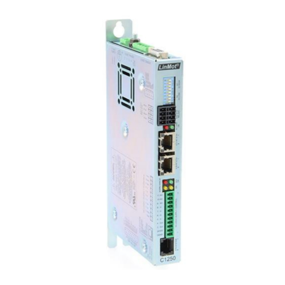
C1200 Servo Drives
Installation Guide
This document applies to the following drives:
C1250-PL-XC-xS
C1250-SE-XC-xS
C1250-IP-XC-xS
not included with the drive!
Drive Connector Set for C1200-0S
Drive Connector Set for C1200-1S
C1250-EC-XC-xS
C1250-PN-XC-xS
C1250-SC-XC-xS
0150-????
0150-????
Advertisement
Table of Contents

Related Manuals for LinMot C1200


Summary of Contents for LinMot C1200
-
Page 1: Installation Guide
C1200 Servo Drives Installation Guide Eine Deutsche Version kann unter http://www.linmot.com bezogen werden! Please visit http://www.linmot.com to check for the latest version of this document! This document applies to the following drives: C1250-PL-XC-xS C1250-EC-XC-xS C1250-SE-XC-xS C1250-PN-XC-xS C1250-IP-XC-xS C1250-SC-XC-xS ATTENTION: The connectors have to be ordered separately and are... - Page 2 NTI AG. LinMot® is a registered trademark of NTI AG. The information in this documentation reflects the stage of development at the time of press and is therefore without obligation.
-
Page 3: Table Of Contents
Preliminary C1200 Installation Guide Table of Content 1 Important Safety Instructions..................4 2 System Overview......................6 3 Interfaces..........................7 4 Functionality and Interfaces...................8 5 Software..........................8 6 Power Supply and Grounding..................9 7 Description of the connectors / Interfaces..............10 7.1 X1..........................10 7.2 X2..........................10 7.3 X3..........................11 7.4 X4 ..........................12... -
Page 4: Important Safety Instructions
• It is up to the user to check whether they can be transferred to the particular applications. NTI AG / LinMot does not accept any liability for the suitability of the procedures and circuit proposals described. LinMot servo drives and the accessory components can include live and moving parts (depending on •... -
Page 5: Electrical Connection
Preliminary C1200 Installation Guide Installation The drives must be installed and cooled according to the instructions given in the corresponding • documentation. The ambient air must not exceed degree of pollution 2 according to EN 61800−5−1. • • Ensure proper handling and avoid excessive mechanical stress. Do not bend any components and do not change any insulation distances during transport or handling. -
Page 6: System Overview
C1200 Installation Guide Preliminary 2 System Overview Typical Servo System C12x0-XX: Servo Drive, Motor and Power Supply. ® Page 6/22 www.LinMot.com NTI AG / LinMot... -
Page 7: Interfaces
Preliminary C1200 Installation Guide Interfaces C12x0-xx-xx-xS-xxx NTI AG / LinMot ® www.LinMot.com Page 7/22... -
Page 8: Functionality And Interfaces
Integrated Safety Functions (-1S Option) STO (2 Safety Relays) ● ● ● ● ● ● ● ● 5 Software The configuration software LinMot-Talk is free of charge and can be downloaded from the LinMot homepage. ® Page 8/22 www.LinMot.com NTI AG / LinMot... -
Page 9: Power Supply And Grounding
In order to assure a safe and error free operation, and to avoid severe damage to system components, all system components must be well grounded to protective earth PE. This includes both LinMot and all other control system components on the same ground bus. -
Page 10: Description Of The Connectors / Interfaces
C1200 Installation Guide Preliminary 7 Description of the connectors / Interfaces 7.1 X1 Motor Phases PWR+ PGND Motor Supply: 72VDC nominal, 24...85VDC Absolute max. Rating: 72VDC +20%. External Fuse: 16AT / min. 100VDC If motor supply voltage exceeds 90VDC, the drive will go into error state. - Page 11 Preliminary C1200 Installation Guide 7.3 X3 Motor Sensor LinMot Motor: Do not connect Do not connect +5VDC Sensor Sine Temp In Do not connect Do not connect AGND Sensor Cosine case Shield DSUB-9 (f) Note: Use +5V (X3.3) and AGND (X3.8) only for motor internal hall sensor supply (max. 100mA).
- Page 12 C1200 Installation Guide Preliminary 7.4 X4 Logig Supply / IO Connection AnIn- X4.11 Configurable Analog Input differential (with X4.10) AnIn+ X4.10 Configurable Analog Input differential (with X4.11) AnIn X4.9 Configurable Analog Input single ended X4.8 Configurable Input X4.7 Configurable Input X4.6...
-
Page 13: X13
Preliminary C1200 Installation Guide 7.6 X13 External Position Sensor Differential Hall Switches ABZ with Hall Switches +5V DC Encoder Alarm case Shield DSUB-15 (f) Position Encoder Inputs ( RS422): Max. counting frequency: 25 Mcounts/s with quadrature decoding, 40ns edge separation Differential Hall Switch Inputs (RS422): Input Frequency: <1kHz... -
Page 14: X19
C1200 Installation Guide Preliminary 7.8 X19 System (Do not connect) (Do not connect) RS232 Rx RS232 Tx (Do not connect) (Do not connect) case Shield RJ-45 Use Adapter cable AC01-RJ45/Df-2.5-RS1 (Art.-No. 0150-2143) for Configuration over RS232. 7.9 X33 Safety Relays (only with the -1S option) -
Page 15: Leds
Preliminary C1200 Installation Guide 7.11 Bootstrap Bootstrap 7.12 LEDs LEDs State Display Green 24V Logic Supply OK Yellow Motor Enabled / Error Code Low Nibble Yellow Warning / Error Code High Nibble Error 7.13 RT BUS LEDs RT Bus LEDs... -
Page 16: Error Codes
18VDC. The meaning of the error codes can be found in the Usermanual_MotionCtrl_Software_SG5 and the user manual of the installed interface software. These documents are provided together with LinMot-Talk configuration software and can be downloaded from www.linmot.com. ®... -
Page 17: Safety Wiring
C1200 Installation Guide 9 Safety Wiring The C1200 drives with the -1S option have internal safety functions: Two Safety relays Ksr in series, which support the supply voltage for the motor drivers. There are also two feedback contacts for each relay. -
Page 18: Physical Dimensions
C1200 Installation Guide Preliminary 10 Physical Dimensions C1200 Series C12xx-xx-XC-0S C12xx-xx-XC-1S single axis drive Width mm (in) 25.3 (1.0) Height mm (in) 166 (6.54) 176 (6.93) Height with fixings mm (in) 206 (8.11) 216 (8.5) Depth mm (in) 106 (4.17) -
Page 19: Power Supply Requirements
Preliminary C1200 Installation Guide 11 Power Supply Requirements Motor Power Supply The calculation of the needed power for the Motor supply is depending on the application and the used motor. The nominal supply voltage is 72- 80 VDC. The possible range is from 24 to 85VDC, for UL from 30 to 85 VDC. -
Page 20: Ordering Information
C1200 Installation Guide Preliminary 13 Ordering Information Item Description Art. Nr. C1200-GP-XC-0S GENERAL PURPOSE Drive (72V/25A) 0150-1882 C1230-DP-XC-0S PROFIBUS DP Drive (72V/25A) 0150-2386 C1250-PL-XC-0S POWERLINK Drive (72V/25A) 0150-1885 C1250-SE-XC-0S SERCOS over ETHERCAT Drive (72V/25A) 0150-1897 C1250-IP-XC-0S ETHERNET IP Drive (72V/25A) -
Page 21: Declaration Of Conformity Ce-Marking
Preliminary C1200 Installation Guide 15 Declaration of Conformity CE-Marking Manufacturer: NTI AG / LinMot ® Haerdlistrasse 15 8957 Spreitenbach Switzerland Tel.: +41 (0)56 419 91 91 Fax: +41 (0)56 419 91 92 Products: LinMot ® drives Type Art.-No. Type Art-No. -
Page 22: Contact Addresses
Elkhorn, WI 53121 Sales and Administration: 877-546-3270 262-743-2555 Tech. Support: 877-804-0718 262-743-1284 Fax: 800-463-8708 262-723-6688 E-Mail: us-sales@linmot.com Web: http://www.linmot-usa.com/ Please visit http://www.linmot.com/ to find the distributor closest to you. Smart solutions are… Page 22/22 www.LinMot.com NTI AG / LinMot ®...
Need help?
Do you have a question about the C1200 and is the answer not in the manual?
Questions and answers