red lion LD200400 Manual

red lion LD200400 Manual

Large display
Hide thumbs Also See for LD200400:

Advertisement

Tel +1 (717) 767-6511
Fax +1 (717) 764-0839
www.redlion.net
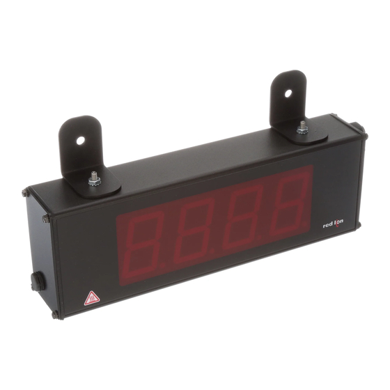
MODEL LD - LARGE DISPLAY
U
L
C
US LISTED
US LISTED
4
IND. CONT . EQ.
51EB

GENERAL DESCRIPTION

The Large Display is a versatile display that can be configured as a single or
dual counter with rate indication, scaling, serial communications and a relay
output. There are also basic models that have a single counter with direction
control only (no scaling or relay output).
The 4 & 6 digit displays are available in either 2.25" or 4" high red LED digits
with adjustable display intensities. The 2.25" high models are readable up to 130
feet. The 4" high models are readable up to 180 feet. All versions are constructed
of a NEMA 4X enclosure in light weight aluminum.
The 6-digit programmable models have two signal inputs and a choice of
eight different count modes. These include bi-directional, quadrature and anti-
coincidence counting, as well as a dual counter mode. When programmed as a
dual counter, each counter has separate scaling and decimal point selection.
Rate indication is available on the programmable models only. The rate
indicator has separate scaling and decimal point selection, along with
programmable display update times. The meter display can be toggled either
manually or automatically between the count and rate values.
The programmable models also come with a Form C relay output and jumper
selectable RS232 or RS485 serial communications.

SAFETY SUMMARY

All safety regulations, local codes and instructions that appear in this and
corresponding literature, or on equipment, must be observed to ensure personal
safety and to prevent damage to either the instrument or equipment connected to
it. If equipment is used in a manner not specified by the manufacturer, the
protection provided by the equipment may be impaired.
CAUTION: Risk of Danger.
Read complete instructions prior to
installation and operation of the unit.
DIMENSIONS In inches (mm)
CAUTION: Risk of electric shock.
2.25" & 4" HIGH RED LED DIGITS
AVAILABLE IN 4 OR 6 DIGIT VERSIONS
SINGLE OR DUAL COUNTER with RATE INDICATOR *
PROGRAMMABLE SCALING AND DECIMAL POINTS *
PROGRAMMABLE USER INPUT *
AC OR DC POWERED
5 AMP FORM C RELAY *
ALUMINUM NEMA 4X CASE CONSTRUCTION
* Programmable models only
The protective conductor terminal is bonded to conductive
parts of the equipment for safety purposes and must be
connected to an external protective earthing system.

SPECIFICATIONS

1. DISPLAY: 2.25" (57 mm) or 4" (101 mm) intensity adjustable Red LED
2. POWER REQUIREMENTS:
AC POWER:
AC Input: 85 to 250 VAC 50/60 Hz, 14 VA
DC Out: 11 to 16 VDC @ 50 mA (consult factory for higher current draw)
DC POWER:
DC Input: 11 to 16 VDC @ 400 mA max, 7 W
3. COUNT INPUT(S):
Counter(s) have DIP switch selectable pull-up (7.8 KΩ) or pull-down
resistors (3.9 KΩ) that determine active high or active low input logic.
Counters are DIP switch selectable for high or low frequency (Damping
capacitor provided for switch contact bounce. Limits input frequency to
50 Hz and input pulse widths to 10 msec min.)
Input A Trigger levels: V
IL
Input B Trigger levels: V
Counter Overflow Indication: Display flashes "
LD200400, LD200600, LD400400, & LD400600:
Count Speed: 35 KHz max. @ 50% duty cycle (no scaling)
LD2006P0 & LD4006P0:
Counter A & B Frequency:
COUNT MODE
CNT UD
RT-CNT
QUAD X1; QUAD X2
QUAD X4; DUAL CNT 16K
ADD/ADD; ADD/SUB
1
Bulletin No. LD-E
Drawing No. LP0607
Released 9/06
= 1.25 V max; V
= 2.75 V min; V
IH
= 1.0 V max; V
= 2.4 V min; V
IL
IH
"
MAX FREQUENCY
35K
25K
22K
20K
PART
X (Length)
Y (Height)
NUMBER
LD2004xx 12 (304.8)
4 (101.6)
LD2006xx 16 (406.4)
4 (101.6)
LD4004xx 20 (508)
7.875 (200)
LD4006xx 26 (660.4)
7.875 (200)
= 28 VDC
MAX
= 28 VDC
MAX
Z (Center)
8 (203.2)
12 (304.3)
16 (406.4)
22 (558.8)

Advertisement

Table of Contents
loading
Need help?

Need help?

Do you have a question about the LD200400 and is the answer not in the manual?

Questions and answers

Subscribe to Our Youtube Channel

Summary of Contents for red lion LD200400

  • Page 1: General Description

    " All safety regulations, local codes and instructions that appear in this and LD200400, LD200600, LD400400, & LD400600: corresponding literature, or on equipment, must be observed to ensure personal Count Speed: 35 KHz max. @ 50% duty cycle (no scaling) safety and to prevent damage to either the instrument or equipment connected to LD2006P0 &...
  • Page 2: Ordering Information

    Torque: 5.3 inch-lbs (0.6 N-m) max. ORDERING INFORMATION TYPE MODEL NO. DESCRIPTION PART NUMBER 2.25" High 4-Digit Red LED Counter LD200400 Basic 2.25" High 6-Digit Red LED Counter LD200600 (No front 4" High 4-Digit Red LED Counter LD400400 panel keys) 4"...
  • Page 3: Emc Installation Guidelines

    2.0 S DIP S ETTING THE WITCHES SETTING THE 8 DIP SWITCHES SWITCH 6 (RESET/USER INPUT) {See Note 1} SNK.: Adds internal 7.8 KΩ pull-up resistor to +12VDC, I = 2.1 mA. To access the switches, remove the right side plate of the meter. A bank of eight SRC.: Adds internal 3.9 KΩ...
  • Page 4: Wiring Overview

    WIRING OVERVIEW Electrical connections are made via pluggable terminal blocks located inside the meter. All conductors should conform to the meter's voltage and current ratings. All cabling should conform to appropriate standards of good installation, local codes and regulations. It is recommended that the power supplied to the meter (DC or AC) be protected by a fuse or circuit breaker.
  • Page 5: Input Wiring

    3.4 INPUT WIRING The Large Display has two signal inputs, A and B. These inputs are wired to All other models are non-programmable and provide Count with Direction terminal block TBB located inside the unit on the right side. Mode only. Input A accepts the count signal, while Input B controls the count direction (up/down).
  • Page 6: Serial Wiring

    Equipment (DCE) receives data on the TXD line and transmits data on the RXD 3.5 SERIAL WIRING line. The PAX emulates a DTE. If the other device connected to the meter also emulates a DTE, the TXD and RXD lines must be interchanged for Serial communications is only available for models LD2006P0 and communications to take place.
  • Page 7: Programming Menu

    5.0 P ROGRAMMING THE ETER OVERVIEW PROGRAMMING MENU PROGRAMMING MODE ENTRY (PAR KEY) PROGRAMMING MODE EXIT (PAR KEY) It is recommended all programming changes be made off line, or before The Programming Mode is exited by pressing the key with Pro NO installation.
  • Page 8 COUNTER A DECIMAL POSITION EXAMPLE: The counter display is used to indicate the total number of feet used in a process. It is necessary to know the number of pulses for the desired units to be displayed. The decimal point is selected to show the resolution in hundredths.
  • Page 9 5.2 MODULE 2 - R ETUP ARAMETERS PARAMETER MENU Module 2 is the programming for the Rate parameters. For maximum input 2. If # of pulse per unit is less than 1, then multiply both Input and Display frequency, Rate Enable should be set to when not in use.
  • Page 10 period will end but the Rate display will be forced to zero. The High Update Time value must be greater than the Low Update Time value. Both values must be greater than 0.0. The input frequency calculated during the sample period, is then shown as a Rate value determined by the scaling calculation.
  • Page 11 5.4 MODULE 4 - S ETPOINT UTPUT ARAMETERS PARAMETER MENU Some parameters will not appear depending on the Setpoint Assignment and Setpoint Output Action selected. SETPOINT ASSIGNMENT SETPOINT OUTPUT POWER-UP STATE Select the display the Setpoint is to be assigned. will restore the output to the same state it was at before the meter was powered down.
  • Page 12 5.5 MODULE 5 - S ERIAL OMMUNICATIONS ARAMETERS PARAMETER MENU Module 5 is the programming module for the Serial Communications ABBREVIATED PRINTING Parameters. These parameters are used to match the serial settings of the meter with those of the host computer or other serial device. The Serial Setup plug jumpers must be properly positioned for RS232 or RS485 serial communications prior to installing the meter.
  • Page 13 Sending Serial Commands and Data Register Identification Chart When sending commands to the meter, a string containing at least one command character must be constructed. A command string consists of a Applicable Value Description MNEMONIC Transmit Details (T and V) Commands command character, a value identifier, numerical data (if writing data to the 6 digit positive/5 digit negative...
  • Page 14 Command Response Time The meter can only receive data or transmit data at any one time (half-duplex At the beginning of time interval t , the meter responds with the first operation). During RS232 transmissions, the meter ignores commands while character of the reply.
  • Page 15: Programming Quick Overview

    PROGRAMMING QUICK OVERVIEW...
  • Page 16: Limited Warranty

    The Company disclaims all liability for any affirmation, promise or representation with respect to the products. The customer agrees to hold Red Lion Controls harmless from, defend, and indemnify RLC against damages, claims, and expenses arising out of subsequent sales of RLC products or products...

This manual is also suitable for:

Ld200600Ld400600Ld2006p0Ld400400Ld4006p0

Table of Contents