red lion LD Series Manual
Large dc volt/current/process display
Hide thumbs
Also See for LD Series:
- Operating manual (20 pages) ,
- User manual (16 pages) ,
- Manual (9 pages)
Table of Contents
Advertisement
Tel +1 (717) 767-6511
Fax +1 (717) 764-0839
www.redlion.net
MODEL LD - LARGE DC VOLT/CURRENT/PROCESS DISPLAY
U L
C C
US LISTED
US LISTED
R
IND. CONT. EQ.
51EB
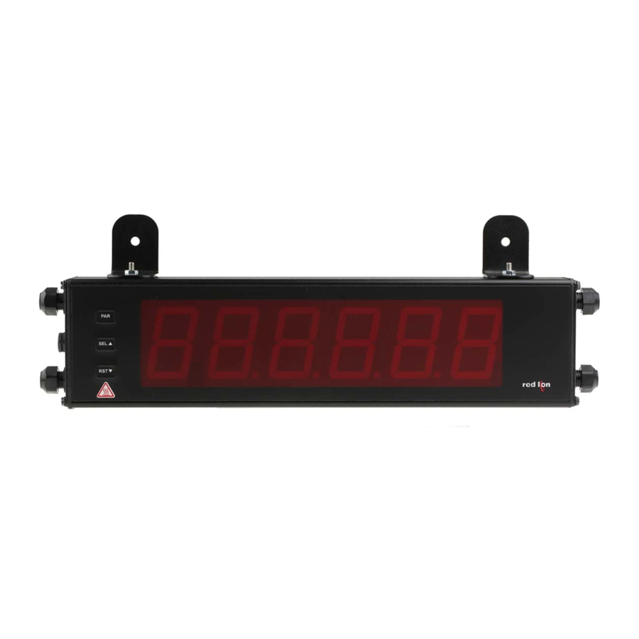
GENERAL DESCRIPTION
The Large Display is a versatile display available as a DC volt, current, or
process meter with scaling, serial communications and dual relay outputs. The 5
digit displays are available in either 2.25" or 4" high red LED digits with
adjustable display intensities. The 2.25" high models are readable up to 130 feet.
The 4" high models are readable up to 180 feet. Both versions are constructed
of a NEMA 4X/IP65 enclosure in light weight aluminum.
All models also come with dual Form C relay outputs and RS232 / RS485
serial communications.
SAFETY SUMMARY
All safety regulations, local codes and instructions that appear in this and
corresponding literature, or on equipment, must be observed to ensure personal
safety and to prevent damage to either the instrument or equipment connected to
it. If equipment is used in a manner not specified by the manufacturer, the
protection provided by the equipment may be impaired.
CAUTION: Risk of Danger.
Read complete instructions prior to
installation and operation of the unit.
The protective conductor terminal is bonded to conductive
parts of the equipment for safety purposes and must be
connected to an external protective earthing system.
ORDERING INFORMATION
MODEL NO. DESCRIPTION
2.25" High 5 Digit Red LED Volt/Current Meter w/
LD2A
Relay Output and RS232/RS485 Serial Comms
4" High 5 Digit Red LED Volt/Current Meter w/
LD4A
Relay Output and RS232/RS485 Serial Comms
LD Plug
Panel Meter Plug for LD models
DIMENSIONS In inches (mm)
AIR PRESSURE STABILIZATION VENT
U L
C
US LISTED
R
3RSD
PROCESS CONTROL EQUIPMENT
CAUTION: Risk of electric shock.
PART NUMBER
LD2A05P0
LD4A05P0
LDPLUG00
X
Z
2.25" & 4" HIGH RED LED DIGITS
PROGRAMMABLE SCALING AND DECIMAL POINTS
PROGRAMMABLE USER INPUT
DUAL 5 AMP FORM C RELAY
ALUMINUM NEMA 4X/IP65 CASE CONSTRUCTION
RS232/RS485 SERIAL COMMUNICATIONS
UNIVERSALLY POWERED
SPECIFICATIONS
1. DISPLAY: 5 digit, 2.25" (57 mm) or 4" (101 mm) intensity adjustable Red LED
(-99999 to 99999)
2. POWER REQUIREMENTS:
AC POWER: 50 to 250 VAC 50/60 Hz, 26 VA
DC POWER: 21.6 to 250 VDC, 11 W
DC Out: +24 VDC @ 100 mA if input voltage is greater than 50 VAC/VDC
+24 VDC @ 50 mA if input voltage is less than 50 VDC
Isolation: 2300 Vrms for 1 min. to all inputs and outputs
3. INPUT RANGES: Jumper Selectable
D.C. Voltages: 200 mV, 2 V, 20 V, 200 V, 10 V
ACCURACY @
INPUT
23
C LESS
RANGE
THAN 85% RH
200 mV
0.1% of span
2 V
0.1% of span
20 V
0.1% of span
200 V
0.1% of span
10 V
0.1% of span
D.C. Currents: 200 A, 2 mA, 20 mA, 200 mA
ACCURACY @
INPUT
23
C LESS
RANGE
THAN 85% RH
200 μΑ
0.1% of span
2 mA
0.1% of span
20 mA
0.1% of span
200 mA
0.1% of span
D.C. Process: 4 to 20 mA, 1 to 5 VDC, 0/1 to 10 VDC
INPUT RANGE
SELECT RANGE
4 - 20 mA
Use the 20 mA range
1 - 5 VDC
Use the 10V range
1 - 10 VDC
Use the 10V range
4. OVERRANGE/UNDERRANGE INDICATION:
Input Overrange Indication: "
Input Underrange Indication: "
Display Overrange/Underrange Indication: "
Y
2.25
(57.15)
1
Bulletin No. LDA-D
Drawing No. LP0673
Released 09/10
MAX
INPUT
INPUT
RESOLUTION
IMPEDANCE
SIGNAL
1.027 M
75 VDC
10 μV
75 VDC
0.1 mV
1.027 M
250 VDC
1 mV
1.027 M
1.027 M
250 VDC
10 mV
538 K
30 V
1 mV
MAX
INPUT
INPUT
RESOLUTION
IMPEDANCE
SIGNAL
15 mA
10 nA
1.111 K
50 mA
0.1 μA
111
150 mA
1 μA
11
1
500 mA
10 μA
OLOL
".
ULUL
".
.....
.....
"/"-
"
PART
X (Length)
Y (Height)
NUMBER
LD2A05P0
16 (406.4)
4 (101.6)
LD4A05P0
26 (660.4)
7.875 (200)
TEMP.
COEFFICIENT
70 ppm /°C
70 ppm /°C
70 ppm /°C
70 ppm /°C
70 ppm /°C
TEMP.
COEFFICIENT
70 ppm /°C
70 ppm /°C
70 ppm /°C
70 ppm /°C
Z (Center)
12 (304.3)
22 (558.8)
Advertisement
Table of Contents


Need help?
Do you have a question about the LD Series and is the answer not in the manual?
Questions and answers