Summary of Contents for red lion PGMMODC1
- Page 1 Product Manual PGMMODC1 Communication enabler Model No. P GMMOD C 1 D rawing No. L P10 97 Ver sion No. 101 Revision Date 19/07...
-
Page 3: Table Of Contents
PGMMODC1 Modbus settings - routing diagram ........ -
Page 4: Warning
General mounting, connection and disconnection of Modbus cable. Troubleshooting the device. VOLTAGE Warning Repair of the device must be done by Red Lion Controls only. CAUTION Symbol identification Triangle with an exclamation mark: Read the manual before installation and commissioning of the device in order to avoid incidents that could lead to personal injury or mechanical damage. -
Page 5: Safety Instructions
When disconnected, the device may be cleaned with a cloth moistened with distilled water. Liability To the extent the instructions in this manual are not strictly observed, the customer cannot advance a demand against Red Lion Controls that would otherwise exist according to the concluded sales agreement. -
Page 6: Applications
Programmed parameters can be protected by a user-defined password. • When mounted on devices that are installed upside down, a menu item allows the display on the PGMMODC1 to be rotated 180o and the up/down buttons to switch function. LP1097... -
Page 7: Mounting On A Iams/Afcm Device
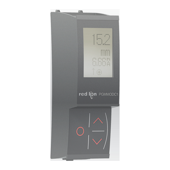
Mounting on a IAMS/AFCM device PGMMODC1 is a detachable display that can be mounted on all IAMS/AFCM fronts for programming and signal monitoring. PGMMODC1 contains a four line LCD dot display Line 1 can e.g. show the scaled process value. -
Page 8: Electrical Specifications
Electrical specifications Environmental conditions: Specifications range ........-20°C to +60°C Storage temperature . -
Page 9: Pgmmodc1 Installation Examples
Access Ethernet Point PGMMOD PGMMOD PGMMOD IAMS IAMS IAMS PLC/DCS AFCM AFCM AFCM Modbus TCP/IP Termination Resistors are not required when talking to other Red Lion devices. However, a 120 Ohm resistor may be required with other master devices. LP1097... -
Page 10: Modbus Basics
RS485 networks, at speeds up to 115,200 bps. The most common speeds are 9,600 bps and 19,200 bps. Modbus RTU is the most widely used industrial protocol and is supported by the PGMMODC1. Modbus RTU: To communicate with a slave device, the master sends a message containing: Device Address - Function Code - Data - Error Check The Device Address is a number from 0 to 247. -
Page 11: Pgmmodc1 Modbus Parameter Settings
1 or 2 stop bits Response delay: 0...1000 ms (0 ms = default) Modbus slave addressing range: 1 - 247 (247 = default address) Modbus Parameter Storage: Saved in non-volatile memory in the PGMMODC1 device (Factory Default Values are marked in bold) LP1097... - Page 12 AFCM Configuration Parameter List Parameter Register Register Read/ Category Type Description Values Name Address Size Write UNSIGNED Defines the GENERAL DEVICE NUMBER AFCM = 16930 (0xAFCM) INTEGER actual device type UNSIGNED GENERAL DEVICE VERSION Product version INTEGER Password UNSIGNED GENERAL PASSWORD for entering Range: 0...9999...
- Page 13 Output type: Programmable pulse is available for: UNSIGNED DC 50% OUTPUT OUTPUT TYPE Frequency < 500 Hz INTEGER Prog Pulse Pulses < 30,000 p/m < 1,800,000 p/hour < 43,200,000 p/day UNSIGNED p/min OUTPUT OUTPUT UNIT Output unit INTEGER p/hour p/day Frequency output Range with frequency selected: 0...25000000...
- Page 14 HELP TEXT UNSIGNED Language for the help GENERAL LANGUAGE INTEGER texts shown in display UNSIGNED CRC16 checksum of the GENERAL CHECKSUM Range 0...65536 INTEGER configuration This counter will count the number of times the Configuration UNSIGNED GENERAL configuration has been Range 0...65536 counter INTEGER...
- Page 15 Table 1: Display units °C mils in/s gal/h °F ft/s p/min in/min µS ft/min p/day mbar /min [blank] in/h ft/h µm mm/s µA l/min m/min mm/s gal/min AFCM Input Types and Ranges Input type Min. value Max. value Standard 0 mA 20 mA 10 V Pt10...Pt1000...
- Page 16 AFCM Process Parameter List Parameter Register Register Read/ Type Description Values Name Address Size Write Range for non-temperature input types: The measured value in 1/10 of °C/°F for DISPLAY LOW...DISPLAY HIGH temperature Input types, or the scaled DISPLAY VALUE 1000 INTEGER Range for temperature input types: equals display value for non-temperature input types...
- Page 17 Description Values Name Address Size Write Enable Modbus communication. If disabled, PGMMODC1 ignores all frames sent ENABLE MODBUS 3000 INTEGER from the Modbus master and the only way to re-enable Modbus communication is by using the PGMMODC1 menu. 2400 BAUD...
-
Page 18: Pgmmodc1 Modbus Settings - Routing Diagram
PGMMODC1 Modbus settings - routing diagram "Monitor" 40.0 0000 (correct) (No) xxxx ---OK--> ---------> PASSW. ---OK--> ADV.SET ---OK--> XXXX 10.4mA (Yes) 9999 0000 (MEM) |----> SETUP -OK-|--> (DISP) |--> DISP (CAL) |--> PASS (SIM) LANG |--> MODB (PASS) |--> (LANG) |-->... - Page 19 SCROLLING HELP TEXTS: Set correct password Enter advanced setup menu? Enter Language setup Enter Password setup Enter Simulation mode Perform Process calibration Enter Display setup Perform Memory operations Enter Modbus setup Enter Rotation setup Enable modbus communication Disable Modbus communication See automatic baudrate detection status Reset Modbus to default? Select Modbus slave address...
-
Page 20: Ordering Information
Ordering information DESCRIPTION PART NUMBER Communication/Programming Module Interface PGMMODC1 LP1097...


Need help?
Do you have a question about the PGMMODC1 and is the answer not in the manual?
Questions and answers