Table of Contents
Advertisement
Quick Links
Tel +1 (717) 767-6511
Fax +1 (717) 764-0839
www.redlion.net
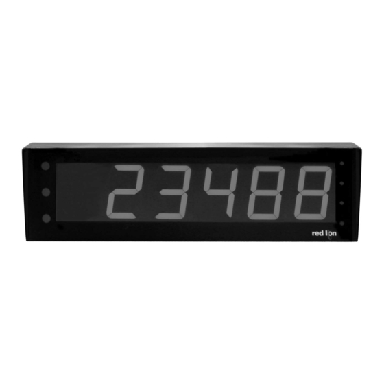
MODEL EPAX- 5 DIGIT EXTRA LARGE PAX DISPLAY FOR ANALOG INPUTS
U
L
C
US LISTED
US LISTED
4
IND. CONT . EQ.
51EB
GENERAL DESCRIPTION
The EPAX is a versatile display that can increase productivity by offering the
plant floor or production area a large visual display of their current status.
Whether your measurement is voltage, current, process, temperature, or strain
gage, the EPAX can satisfy your requirement. The EPAX accepts various analog
inputs through the use of input modules (MPAX) which allow the unit to adapt
to most any application. The MPAX Modules offer the same features as our
highly successful PAX Series Panel Meters. Additional plug-in option cards can
add alarms, analog output, and communication/bus capabilities, making the
EPAX a truly Intelligent Panel Meter.
SAFETY SUMMARY
All safety regulations, local codes and instructions that appear in this and
corresponding literature, or on equipment, must be observed to ensure personal
safety and to prevent damage to either the instrument or equipment connected
to it. If equipment is used in a manner not specified by the manufacturer, the
protection provided by the equipment may be impaired.
The protective conductor terminal is bonded to conductive
parts of the equipment for safety purposes and must be
connected to an external protective earthing system.
CAUTION: Risk of Danger
Read complete instructions prior to
installation and operation of the unit.
DIMENSIONS In inches (mm)
CAUTION: Risk of electric shock.
LARGE LED DISPLAY READABLE TO 180 FEET
VARIOUS ANALOG INPUT MODULES;
DC VOLTAGE AND CURRENT
PROCESS SIGNALS
TRUE RMS VOLTAGE AND CURRENT
THERMOCOUPLE OR RTD
STRAIN GAGE/BRIDGE
ALARMS, ANALOG OUTPUT, AND COMMUNICATION
PROGRAMMABLE USER INPUTS
UNIVERSAL AC POWERED (85 to 250 VAC)
CRIMSON PROGRAMMING SOFTWARE
NEMA 4X/IP65
SPECIFICATIONS
Additional specifications, wiring, programming, and information for the
individual MPAX models are contained in the corresponding standard PAX
literature. This PAX literature is shipped with the ordered MPAX model.
1. DISPLAY: 4" (101 mm) Red LED
5-Digit (EPAX0500): -19999 to 99999
2. POWER REQUIREMENTS:
AC MPAX Modules: 85 to 250 VAC, 50/60 Hz, 18 VA
EPAX Display: 85 to 250 VAC, 50/60 Hz, 10 VA
3. INPUT: Accepts analog input modules, see "Selecting Your Display
Components and Option Cards."
4. ANNUNCIATORS:
Display Indication: Three vertical dots on the left side of the unit identify
the displays for the following modes:
TOP
MIDDLE
BOTTOM
Setpoint Indication: Four vertical dots on the right side of the unit identify
the setpoint "ON" condition, with SP 1 being the top position through SP
4 at the bottom.
5. EPAX Programming: The unit is a large display, designed to be remotely
mounted. Therefore, the unit does not have a programming keypad. Unit
programming should be accomplished by one of the following methods:
Rear Terminal Block: External switches can be wired via the terminal block
to allow unit programming. A minimum of 3 switches would be required.
Optional Programming Remote (EPAXPGM0): This option provides a 10
foot interconnecting cable and programming box. The Programming
Remote contains buttons similar to the PAX, allowing easy programming
of the EPAX display.
Optional Serial Programming: Like all PAX units, you can purchase an RS232
or RS485 Comms Card and program the unit via Crimson, a Windows
based software program.
1
Bulletin No. EPAX5-D
Drawing No. LP0536
Released 6/07
Maximum
Minimum
Total
®
Advertisement
Table of Contents

Related Manuals for red lion EPAX-5


Summary of Contents for red lion EPAX-5
- Page 1 Bulletin No. EPAX5-D Drawing No. LP0536 Released 6/07 Tel +1 (717) 767-6511 Fax +1 (717) 764-0839 www.redlion.net MODEL EPAX- 5 DIGIT EXTRA LARGE PAX DISPLAY FOR ANALOG INPUTS LARGE LED DISPLAY READABLE TO 180 FEET VARIOUS ANALOG INPUT MODULES; DC VOLTAGE AND CURRENT PROCESS SIGNALS TRUE RMS VOLTAGE AND CURRENT THERMOCOUPLE OR RTD...
- Page 2 6. CERTIFICATIONS AND COMPLIANCES: 9. MODULE INSTALLATION: SAFETY 24-pin shrouded connector on EPAX engages connector on MPAX module UL Recognized Component, File #E179259, UL61010A-1, CSA C22.2 upon installation. Shroud ensures proper alignment by providing a lead-in for No. 1010-1 the module connector. Recognized to U.S.
-
Page 3: Assembling The Display
1.0 ASSEMBLING THE DISPLAY CAUTION: The MPAX main circuit board and the option cards WARNING: Exposed line voltage exists on the MPAX main circuit contain static sensitive components. Before handling the module board and the option cards. DO NOT apply power to the or the cards, discharge static charges from your body by module OR load circuits until the module is properly installed touching a grounded bare metal object. -
Page 4: Installing The Display
2.0 INSTALLING THE DISPLAY EPAX DISPLAY INSTALLATION The EPAX display is intended to be mounted into a panel or enclosure. The display is provided DIMENSIONS In inches (mm) with a gasket to provide a water-tight seal. The recommended minimum panel thickness for NEMA 4/IP65 sealing is 0.060"... - Page 5 3.0 WIRING AND PROGRAMMING THE DISPLAY Once assembled, the EPAX and MPAX have all the same functions and capabilities of our PAX Series Intelligent Panel Meters. Therefore, you will find the appropriate PAX information packed with the MPAX Module. Simply follow the instructions to wire and program the display for your application.
- Page 6 NEMA 4/IP65 LARGE DISPLAY ENCLOSURE & SHROUD FOR EPAX LIGHT-WEIGHT ALUMINUM CONSTRUCTION COMPLETELY SEALED FOR WASH-DOWN MOUNTING CHANNELS FOR VERSATILE INSTALLATION DESCRIPTION The NEMA 4/IP65 Large Display Enclosure is designed to protect the EPAX from dust and hose directed water, when properly installed. This light-weight all aluminum unit utilizes welded seams and neoprene gaskets to meet NEMA 4/IP65 requirements.
- Page 7 ASSEMBLY AND INSTALLATION PROCEDURE 1. Install the two mounting channels on the enclosure housing using the four #8-32 screws provided and then insert the strut nuts (provided). Invert enclosure if base mounting. 2. If the wiring is to be routed through the housing, make sure that the mounting channels are oriented properly before drilling, so the Display will be readable.
-
Page 8: Ordering Information
The Company disclaims all liability for any affirmation, promise or representation with respect to the products. The customer agrees to hold Red Lion Controls harmless from, defend, and indemnify RLC against damages, claims, and expenses arising out of subsequent sales of RLC products or products...
Need help?
Do you have a question about the EPAX-5 and is the answer not in the manual?
Questions and answers