Table of Contents
Advertisement
Quick Links
Tel +1 (717) 767-6511
Fax +1 (717) 764-0839
www.redlion.net
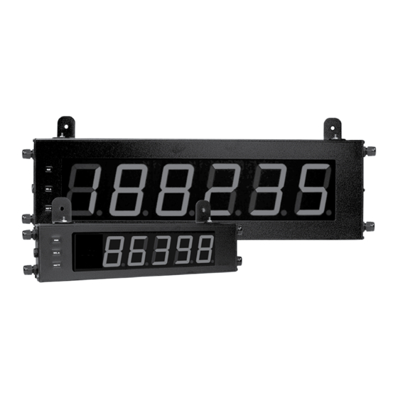
MODEL LD - LARGE DISPLAY
U L
C C
US LISTED
US LISTED
R
IND. CONT. EQ.
51EB
GENERAL DESCRIPTION
The Large Display is a versatile display that can be configured as a single or
dual counter with rate indication, scaling, serial communications and a dual
relay output. There are also basic models that have a single counter with
direction control only (no scaling or relay output).
The 4 & 6 digit displays are available in either 2.25" or 4" high red LED digits
with adjustable display intensities. The 2.25" high models are readable up to 130
feet. The 4" high models are readable up to 180 feet. All versions are constructed
of a NEMA 4X/IP65 enclosure in light weight aluminum.
The 6-digit programmable models have two signal inputs and a choice of
eight different count modes. These include bi-directional, quadrature and anti-
coincidence counting, as well as a dual counter mode. When programmed as a
dual counter, each counter has separate scaling and decimal point selection.
Rate indication is available on the programmable models only. The rate
indicator has separate scaling and decimal point selection, along with
programmable display update times. The meter display can be toggled either
manually or automatically between the count and rate values.
The programmable models also come with a dual Form C relay output and
RS232 or RS485 serial communications. The outputs can activate based on
either counter or rate setpoint values. An internal batch counter can be used to
count setpoint output activations.
SAFETY SUMMARY
All safety regulations, local codes and instructions that appear in this and
corresponding literature, or on equipment, must be observed to ensure personal
safety and to prevent damage to either the instrument or equipment connected to
it. If equipment is used in a manner not specified by the manufacturer, the
protection provided by the equipment may be impaired.
Do not use this unit to directly command motors, valves, or other actuators
not equipped with safeguards. To do so can be potentially harmful to persons or
equipment in the event of a fault to the unit.
CAUTION: Risk of Danger.
Read complete instructions prior to
installation and operation of the unit.
DIMENSIONS In inches (mm)
AIR PRESSURE STABILIZATION VENT
CAUTION: Risk of electric shock.
X
Z
2.25" & 4" HIGH RED LED DIGITS
AVAILABLE IN 4 OR 6 DIGIT VERSIONS
SINGLE OR DUAL COUNTER with RATE INDICATOR *
PROGRAMMABLE SCALING AND DECIMAL POINTS *
BUILT-IN BATCH COUNTING CAPABILITY *
PROGRAMMABLE USER INPUT *
UNIVERSALLY POWERED
DUAL 5 AMP FORM C RELAY *
ALUMINUM NEMA 4X CASE CONSTRUCTION
* Programmable models only
The protective conductor terminal is bonded to conductive
parts of the equipment for safety purposes and must be
connected to an external protective earthing system.
SPECIFICATIONS
1. DISPLAY: 2.25" (57 mm) or 4" (101 mm) intensity adjustable Red LED
2. POWER REQUIREMENTS:
AC POWER: 50 to 250 VAC 50/60 Hz, 26 VA
DC POWER: 21.6 to 250 VDC, 11 W
DC OUT: +24 VDC @ 100 mA if input voltage is greater than 50 VAC/VDC
+24 VDC @ 50 mA if input voltage is less than 50 VDC
Isolation: 2300 V
for 1 min. to all inputs and outputs
RMS
3. COUNT INPUT(S):
Counter(s) have DIP switch selectable pull-up (7.8 K) or pull-down
resistors (3.9 K) that determine active high or active low input logic.
Counters are DIP switch selectable for high or low frequency (Damping
capacitor provided for switch contact bounce. Limits input frequency to 50
Hz and input pulse widths to 10 msec min.)
Input A Trigger levels: V
= 1.25 V max; V
IL
Input B Trigger levels: V
= 1.0 V max; V
IL
Overflow Indication: Display "
LD200400, LD200600, LD400400, & LD400600:
Count Rate: 25 KHz max. @ 50% duty cycle (no scaling)
LD2006P0 & LD4006P0:
Maximum Count Rates: 50% duty cycle, count mode dependent.
With setpoints disabled: 25 KHz, all modes except Quadrature x4 (23 KHz).
With setpoint(s) enabled: 20 KHz, all modes except Dual Counter (14
KHz), Quadrature x2 (13 KHz) and Quadrature x4 (12 KHz).
4. RATE INPUT: Models LD2006P0 & LD4006P0 only
Display Range: 0 to 99999
Min Freq.: 0.01 Hz
Max Freq.: See Count Input specification
Accuracy: ±0.01%
Rate Overflow Indication: Display "
Y
2.25
(57.15)
1
Bulletin No. LD-K
Drawing No. LP0607
Released 05/11
= 2.75 V min; V
IH
MAX
= 2.4 V min; V
IH
MAX
" alternates with overflowed count value.
"
PART
X (Length)
Y (Height)
NUMBER
LD2004xx 12 (304.8)
4 (101.6)
LD2006xx 16 (406.4)
4 (101.6)
LD4004xx 20 (508)
7.875 (200)
LD4006xx 26 (660.4)
7.875 (200)
= 28 VDC
= 28 VDC
Z (Center)
8 (203.2)
12 (304.3)
16 (406.4)
22 (558.8)
Advertisement
Table of Contents

Related Manuals for red lion LD


Summary of Contents for red lion LD
-
Page 1: General Description
Released 05/11 Tel +1 (717) 767-6511 Fax +1 (717) 764-0839 www.redlion.net MODEL LD - LARGE DISPLAY 2.25" & 4" HIGH RED LED DIGITS AVAILABLE IN 4 OR 6 DIGIT VERSIONS SINGLE OR DUAL COUNTER with RATE INDICATOR * ... -
Page 2: Ordering Information
RS232/RS485 Serial Communications (With front 4" High 6-Digit Red LED Count/Rate Indicator w/ dual Relay Output & RS232/ panel keys) LD4006P0 RS485 Serial Communications LD Plug Panel Meter Plug for LD models LDPLUG00 1.0 I NSTALLING THE ETER INSTALLATION MOUNTING INSTRUCTIONS The meter meets NEMA 4X/IP65 requirements when properly installed. -
Page 3: Wiring The Meter
2.0 S DIP S ETTING THE WITCHES SETTING THE 8 DIP SWITCHES SWITCH 6 (RESET/USER INPUT) {See Note 1} SNK.: Adds internal 7.8 K pull-up resistor to +12VDC, I = 2.1 mA. To access the switches, remove the right side plate of the meter. A bank of SRC.: Adds internal 3.9 K... -
Page 4: Wiring Overview
WIRING OVERVIEW Electrical connections are made via pluggable terminal blocks located inside the meter. All conductors should conform to the meter's voltage and current ratings. All cabling should conform to appropriate standards of good installation, local codes and regulations. It is recommended that the power supplied to the Front meter (DC or AC) be protected by a fuse or circuit breaker. -
Page 5: Input Wiring
3.4 INPUT WIRING The Large Display has two signal inputs, A and B. These inputs are wired to All other models are non-programmable and provide Count with Direction terminal block TBB located inside the unit on the right side. Mode only. Input A accepts the count signal, while Input B controls the count direction (up/down). -
Page 6: Programming Menu
LD METER (DTE) DB25 DB25 as 10M baud (the LD is limited to 38.4k baud). The same pair of wires is used to both transmit and receive data. RS485 is therefore always half-duplex, that is, data cannot be received and transmitted simultaneously. -
Page 7: Parameter Menu
5.1 MODULE 1 - I NPUT ETUP ARAMETERS 1-INP PARAMETER MENU b-bAt INP Ab A-dPt A-Scf A-rSt A-dir Cnt Ld Count Counter A Counter A Counter A Counter A Counter A Counter B Mode Decimal Point Scale Factor Reset Action Count Direction... - Page 8 COUNTER A COUNT LOAD VALUE EXAMPLE: The counter display is used to indicate the total number of feet used in a process. It is necessary to know the number of pulses for the desired units to be displayed. The decimal point is selected to show the resolution in ...
- Page 9 5.2 MODULE 2 - R ETUP ARAMETERS 2-rAtE PARAMETER MENU rt-Enb rt-dPt StYLE rt-dSP rt-INP LO-Udt HI-Udt Rate Rate Decimal Rate Input Rate Scaling Rate Scaling Rate Low Rate High Enable Point Scaling Style Display Value Input Value Update Time Update Time RATE ENABLE RATE LOW UPDATE TIME (DISPLAY UPDATE)
- Page 10 INPUT FREQUENCY CALCULATION The meter determines the input frequency by summing the number of falling edges received during a sample period of time. The sample period begins on the first falling edge. At this falling edge, the meter starts accumulating time towards Low Update and High Update values.
- Page 11 FACTORY SERVICE OPERATIONS RESTORE FACTORY DEFAULT SETTINGS Entering Code 66 will overwrite all user settings with the factory default Select to perform either of the Factory Service Operations shown below. ...
- Page 12 SETPOINT ASSIGNMENT SETPOINT BOUNDARY TYPE Select the display the Setpoint is to be assigned. High Acting Boundary Type activates the output when the assigned display value ( ) equals or exceeds the Setpoint value.
- Page 13 RS485 applications. This parameter is used to copy all the program settings from one LD meter ABBREVIATED PRINTING directly to another LD meter(s), through the serial terminal block connections ...
- Page 14 To connect the LD meters for copying, refer to section 3.5 Serial Wiring for 4. During the copy process (~ 2 sec.), the master meter displays an upload message details. The meter shown in the figures as LD METER will be the master.
-
Page 15: Communication Format
Abbreviated Transmission Meter Response Examples: Byte Description 1. Node address = 17, full field response, Counter A = 875 12 byte data field, 10 bytes for number, one byte for sign, 1-12 17 CTA 875 <CR><LF> one byte for decimal point <CR>... -
Page 16: Programming Quick Overview
PROGRAMMING QUICK OVERVIEW...
Need help?
Do you have a question about the LD and is the answer not in the manual?
Questions and answers