Table of Contents
Advertisement
Quick Links
Advertisement
Table of Contents

Related Manuals for Fluke 1560 Black Stack


Summary of Contents for Fluke 1560 Black Stack
- Page 1 Hart Scientific 1560 Black Stack Thermometer Readout User’s Guide Rev. 932001...
- Page 2 Limited Warranty & Limitation of Liability Each product from Fluke Corporation, Hart Scientific Division ("Hart") is warranted to be free from de- fects in material and workmanship under normal use and service. The warranty period is 2 years for the Black Stack.
-
Page 3: Table Of Contents
Table of Contents 1 Before You Start ......1 Symbols Used ......1 Safety Information . - Page 4 Making Measurements ..... . . 23 4.5.1 Selecting Input Channels ......23 4.5.2 Selecting the Probe Characterization .
- Page 5 5.5.5 System Reset ........60 6 Digital Communications Interface ....63 Overview .
- Page 6 6.5.4.11 CALCulate[n]:CONVert:SNUMber? ......86 6.5.4.12 CALCulate[n]:CONVert:SRLow <sub-range_number>....86 6.5.4.13 CALCulate[n]:CONVert:SRLow? .
- Page 7 6.5.10.2 *ESE <numeric_value>....... . 102 6.5.10.3 *ESE? ......... 103 6.5.10.4 *ESR? .
- Page 8 Description ......125 Specifications ......125 Operation.
- Page 9 12.2.1 Calculating Accuracy ......148 12.3 Operation......149 12.3.1 Connecting a Thermocouple.
- Page 10 14.4.7 Device Setup Commands ......166 14.5 Serial Communication Device ....167 14.5.1 Connection .
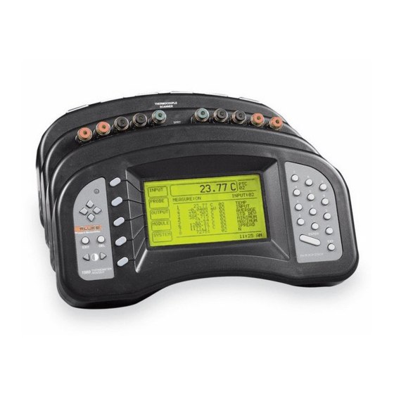
- Page 11 Figures Figure 1 1560 Black Stack Thermometer with Two Modules Attached ..5 Figure 2 System Diagram ......8 Figure 3 Typical Display .
- Page 12 Tables Table1 International Electrical Symbols ..... 1 Table 2 Soft-key Menu System ......30 Table 3 Conversion Types .
-
Page 13: Before You Start
1 Before You Start Symbols Used Before You Start Symbols Used Table 1 lists the International Electrical Symbols. Some or all of these symbols may be used on the instrument or in this manual. Table1 International Electrical Symbols Symbol Description AC-DC Battery Double Insulated... -
Page 14: Safety Information
1560 Thermometer Readout User’s Guide Canadian Standards Association OVERVOLTAGE (Installation) CATEGORY II, Pollution Degree 2 per IEC1010-1 re- fers to the level of Impulse Withstand Voltage protection provided. Equipment of OVERVOLTAGE CATEGORY II is energy-consuming equipment to be supplied from the fixed installation. -
Page 15: Cautions
Keep the probe wires clean and away from fluids. Authorized Service Centers Please contact one of the following authorized Service Centers to coordinate service on your Hart product: Fluke Corporation, Hart Scientific Division 799 E. Utah Valley Drive American Fork, UT 84003-9775 Phone: +1.801.763.1600 Telefax: +1.801.763.1010... - Page 16 22 Jianguomenwai Dajie Chao Yang District Beijing 100004, PRC CHINA Phone: +86-10-6-512-3436 Telefax: +86-10-6-512-3437 E-mail: xingye.han@fluke.com.cn Fluke South East Asia Pte Ltd. Fluke ASEAN Regional Office Service Center 60 Alexandra Terrace #03-16 The Comtech (Lobby D) 118502 SINGAPORE Phone: +65 6799-5588 Telefax: +65 6799-5588 E-mail: antng@singa.fluke.com...
-
Page 17: Introduction
1560 and the measurement process in greater detail. Features The 1560 Black Stack has a unique modular design that consists of a base con- troller and add-on modules. The base controller is the “brain” of the system. It directs all operations and provides control signals and power for the modules. - Page 18 Measurements can be stored in memory and printed later. The 1560 Black Stack is designed to measure a variety of sensors: platinum re- sistance thermometers (PRTs) or resistance temperature detectors (RTDs), stan- dard platinum resistance thermometers (SPRTs), thermistors, thermocouples, and others.
-
Page 19: Components
Components Figure 2 shows the system layout of the 1560 Black Stack. The components are described in the following sections. 2.2.1 Base Microprocessor The base microprocessor is the main controller of the system. -
Page 20: Figure 2 System Diagram
1560 Thermometer Readout User’s Guide Figure 2 System Diagram... -
Page 21: Figure 3 Typical Display
2 Introduction Components well as a variety of other important information. It also helps the user select functions using the soft-keys. Figure 3 shows an example of how the display might look. The various parts of the display are described following. Figure 3 Typical Display Primary display window The primary display window presents the most recent measurement. -
Page 22: Figure 4 Typical Graph Mode Display
1560 Thermometer Readout User’s Guide Soft-keys Five soft-key labels are located along the left edge of the display next to the soft-key buttons. The soft-key labels and the functions of the soft-key buttons change depending on the selected menu. Statistical display window The large area in the center of the display has various uses. -
Page 23: Buttons
2 Introduction Components duced and displayed on the screen in the primary display window it is also displayed on the top of the text output window (see Section 5.3.1.5). Each line containing previous measurements is scrolled down one line. Measurements are displayed with the input channel number first, then the measurement value, the units, and the time the measurement was acquired. -
Page 24: Serial Rs-232 Interface
1560 Thermometer Readout User’s Guide lower menu to a higher menu. In any window, pressing EXIT will immediately exit the window and skip to the next window or return to the menu. If a param- eter is entered or changed and EXIT is pressed before ENTER, the change will be ignored. -
Page 25: Add-On Modules
2 Introduction Components 2.2.2 Add-On Modules Add-on modules provide specific functionality required by the user. Up to eight modules can be attached to the base. A single module may contain multiple in- dependent devices, each having a different function. For instance, the extended communication module contains a GPIB device for parallel communications, a Centronics interface device for printing to a printer, and an analog output de- vice for output of measurement data as an analog voltage. -
Page 26: Data Processing
Data Processing This section explains how measurement data is sampled, processed, and output within the 1560 Black Stack system. Data flow is diagramed in Figure 5 with the details explained below. 2.3.1 Inputs Measurement data originates with input devices such as the SPRT module. -
Page 27: Figure 5 Data Flow
2 Introduction Data Processing Figure 5 Data Flow... -
Page 28: Unit Conversion
1560 Thermometer Readout User’s Guide pendently specified for each input channel (see Section 5.2.1). Some conver- sions, namely those for thermocouples, may use the CJC temperature read from the module with the measurement. Converted measurements are immediately passed to the unit conversion block. 2.3.5 Unit Conversion The unit conversion block converts measurements to the appropriate units (see... -
Page 29: Display Data Fields
2 Introduction Data Processing 2.3.12 Display Data Fields In statistical mode, the center display window contains eight programmable data fields. These can display measurements from any input channel as well as the results of statistical calculations (see Section 5.3.1.1 and 5.3.1.2). Measure- ments are displayed with the channel number, units, time, and a label identify- ing the type of calculation. -
Page 30: Specifications And Environmental Conditions
3 Specifications and Environmental Conditions Specifications Specifications and Environmental Conditions Specifications Power 100 to 230VAC (±10%), 50/60 Hz, .5A Weight (base only) 4.5 lbs. Maximum number of modules Maximum number of input channels * Specifications for modules can be found in the chapters for the individual modules. -
Page 31: General Operation
Installing New Modules General Operation This section explains basic operation of the 1560 Black Stack. Operation of the 1560 is explained in greater detail in subsequent sections: Section 5 explains each of the functions available with the soft-keys and Section 6 explains the communication commands used to operate the 1560 remotely. - Page 32 1560 Thermometer Readout User’s Guide The procedure for attaching a new module is as follows: Turn off power to the 1560. Disconnect the power cord of the 1560 from the mains supply and disconnect the power cord from the back of the 1560.
-
Page 33: Ac Power Source
4 General Operation AC Power Source AC Power Source The 1560 requires an AC power source. See Section 3.1, Specifications, for deatils. The power supply automatically adjusts to the mains voltage. The 1560 may draw up to 0.5A. The AC power cord attaches to the 1560 at the power socket located at the rear of the second section of the base. -
Page 34: Figure 7 Channel Numbering
CH. 2 SPRT Module SPRT SPRT INPUT —123.4507 C PROBE MEASURE:ON INPUT:01 113.0 OUTPUT MODULE EXIT SYSTEM – 6.0 min 6.0 min 130.0 11:37 AM 11:37 AM E N T The 1560 BLACK STACK A Fluke Company Figure 7 Channel numbering... -
Page 35: Selecting The Probe Characterization
4 General Operation Making Measurements cations. They are not marked on modules since the locations may change de- pending on how modules are attached. Channel numbers are assigned in sequence, starting with 1, from left to right, front to back. The left-most chan- nel on the first module is channel 1, the next channel on the right is channel 2, etc. -
Page 36: Measuring One Channel
1560 Thermometer Readout User’s Guide EDIT SPRT 01 PROBE SER#: 566-011 CONVERSION: ITS-90 LO RANGE: 4 HI RANGE: 7 R[273]: 25.546738 A[4]: -1.5763669E-4 Press EXIT twice to return to the soft-key menu. The coefficients you entered can be verified by using the TEST CONV soft-key function (see Section 5.2.3) to compare calculated temperatures to expected values from a calibration report. - Page 37 4 General Operation Making Measurements function (see Section 5.3.3). To show multiple lines of selected data, select the STAT WINDOW function in the DISP WINDOW sub-menu (see Section 5.3.1). The type of data is selected using the SET FIELDS function (Section 5.3.2).
-
Page 38: Soft-Key Functions
5 Soft-Key Functions Input Menu Soft-Key Functions The soft-key menu system provides a convenient method of accessing a large number of functions from the front panel with only a few buttons. The soft-keys next to the display are used to select particular functions. Labels on the display next to the soft-key identify the functions. - Page 39 1560 Thermometer Readout User’s Guide Table 2 Soft-key Menu System INPUT MEAS Set measurement control parameters PRIM CHAN Select the primary input channel SCAN CHAN Select input channels for scanning SCAN MODE Select the scan mode AVER Set input averaging PROBE EDIT PROBE Edit the probe parameters for a channel...
-
Page 40: Primary Channel
5 Soft-Key Functions Input Menu The DELAY parameter (0 to 32,767) sets the minimum delay time, in seconds, between each measurement. Use the numeric buttons to enter a value and press ENTER. Measurements may take longer than the specified delay time, if nec- essary. -
Page 41: Scan Mode
1560 Thermometer Readout User’s Guide SELECT CHANNELS TO SCAN >SPRT 01: ON SPRT 02: ON 03: ON 04: ON 05: ON 06: ON Selecting channels to scan will also set the SCAN MODE to SCAN CHAN. 5.1.4 Scan Mode The SCAN MODE soft-key is used to set the input channel scan mode. The available options for SCAN MODE are as follows: PRIM CHAN: measure the primary channel only. -
Page 42: Probe Menu
5 Soft-Key Functions Probe Menu The AVERAGE parameter determines whether averaging is disabled (OFF) or enabled (ON). Use the LR buttons to select ON or OFF for AVERAGE and press ENTER. The COUNT parameter determines the number of raw measurements that are averaged to produce the displayed measurement. -
Page 43: Conversion Types
1560 Thermometer Readout User’s Guide and the probe serial number. The channel is selected using the UD buttons and pressing ENTER. SELECT A CHANNEL TO EDIT >SPRT 01, PROBE 566-011 SPRT 02, PROBE 566-012 03, PROBE 1341 04, PROBE 1342 05, PROBE 1343 06, PROBE 1344 After the channel is selected, a new window appears allowing you to edit the... - Page 44 5 Soft-Key Functions Probe Menu Sensor Type Conversion options SPRT, PRT, and RTD R(Ω) ITS-90 (default) W(T90) IPTS-68 POLYNOMIAL Thermistor R(Ω) THRM T(R) THRM R(T) (default) POLYNOMIAL 2564 module also has ITS-90 W(T90) IPTS-68 Thermocouple TC-B TC-E TC-J TC-K (default) TC-N TC-R TC-S...
-
Page 45: R(Ω) Conversion
1560 Thermometer Readout User’s Guide 5.2.1.1 R(Ω) Conversion EDIT SPRT 01 PROBE SER#: 1 CONVERSION: R(Ω) The R(Ω) conversion displays the measurement as resistance in ohms rather than temperature. 5.2.1.2 ITS-90 Conversion EDIT SPRT 01 PROBE SER#: 1 CONVERSION: ITS-90 LO RG: 4, 83k - 273k HI RG: 7, 273k - 933k RTPW: 25.546738... -
Page 46: W(T ) Conversion
5 Soft-Key Functions Probe Menu 5.2.1.3 ) Conversion EDIT SPRT 01 PROBE SER#: 1 CONVERSION: W(T90) RTPW: 25.412294 The W(T90) conversion displays the measurement in ITS-90 W(T ) values rather than temperature. The one user-defined parameter for the W(T ) conver- sion is the triple point of water resistance, RTPW. -
Page 47: Callendar-Van Dusen Conversion
1560 Thermometer Readout User’s Guide 5.2.1.5 Callendar-Van Dusen Conversion EDIT SPRT 01 PROBE SER#: 1 CONVERSION: CVD R0: 100.0 ALPHA: 0.00385 DELTA: 1.507 BETA: 0.111 The following equations are used for the Callendar-Van Dusen conversion: ⎧ ⎧ ⎫ ⎡ ⎤ ⎛... -
Page 48: Rtd Polynomial Conversion
5 Soft-Key Functions Probe Menu 5.2.1.6 RTD Polynomial Conversion EDIT SPRT 01 PROBE SER#: 1 CONVERSION: POLYNOMIAL A[0]: -35.540960 A[1]: 0.36568108 A[2]: -1.884784E-4 A[3]: 7.26691E-6 The following equation is used for the RTD polynomial conversion: ∑ ° ( )[ The user-defined parameters for the polynomial conversion are A[0] (a through A[10] (a ). -
Page 49: Thermistor R(T) Conversion
1560 Thermometer Readout User’s Guide 5.2.1.8 Thermistor R(T) Conversion EDIT STHR 01 PROBE SER#: 1 CONVERSION: THRM-R(T) B[0]: -35.540960 B[1]: 0.36568108 B[2]: -1.884784E-4 B[3]: 7.26691E-6 The following Steinhart-Hart equation is used for the thermistor R(T) conversion: − − − r T K ( [ ]) exp[ The user-defined parameters for the thermistor R(T) conversion are B[0] (B... -
Page 50: Standard Thermocouple Conversions
5 Soft-Key Functions Probe Menu 5.2.1.10 Standard Thermocouple Conversions EDIT TCS 03 PROBE SER#: 1 CONVERSION: TC-K CJC: INTERNAL CJC TEMP: 0.0 CAL PTS: 3 T1: 500.0 NOTE: An Application Note for use of Tungsten-Rhenium and other thermocouples is available at www.hartscientific.com. Standard thermocouple conversions include types B, E, J, K, N, R, S, T, and gold-platinum (AU/PT). -
Page 51: Thermocouple Table Conversion
1560 Thermometer Readout User’s Guide Conversions for each of the thermocouple types accept optional calibration data. This can be used to improve the measurement accuracy. CAL PTS indi- cates the number of calibration points used, up to three. Tn is the temperature of the point. -
Page 52: Thermocouple Polynomial Conversion
5 Soft-Key Functions Probe Menu 5.2.1.12 Thermocouple Polynomial Conversion EDIT TCS 03 PROBE SER#: 1 CONVERSION: TC-POLY CJC: INTERNAL C0: 0.0 CJC TEMP: 0.0 C1: 0.038562 NOTE: An Application Note for use of Tungsten-Rhenium and other thermocouples is available at www.hartscientific.com. The following equation is used for the thermocouple polynomial conversion: ∑... - Page 53 1560 Thermometer Readout User’s Guide SELECT THE CHANNEL TO COPY FROM >SPRT 01, PROBE 566-011 SPRT 02, PROBE 566-012 03, PROBE 1341 04, PROBE 1342 05, PROBE 1343 06, PROBE 1344 After the source channel is selected, a window appears requesting you to select the destination channel.
-
Page 54: Test Conversion
5 Soft-Key Functions Output Menu 5.2.3 Test Conversion The TEST CONV soft-key allows you to test the probe characterization algo- rithm and characterization coefficients for a specific probe. You must first se- lect the channel number of the probe. A window appears requesting you to select the input channel. -
Page 55: Display Window Menu
1560 Thermometer Readout User’s Guide 5.3.1 Display Window Menu The DISP WINDOW sub-menu provides functions for controlling the display of data on the front panel screen. The soft-key functions that appear in this sub-menu are STAT WINDOW, SET FIELDS, GRAPH WINDOW, CLEAR GRAPH, and SCROLL WINDOW. - Page 56 5 Soft-Key Functions Output Menu SELECT A DISPLAY FIELD DISPLAY FIELD: 1 Next, a new window appears allowing you to select the data for the given field. SELECT THE DATA FOR FIELD 1 +CHANNEL: 1 –CHANNEL: 0 CALCULATION: TEMP CHANNEL 0=NONE CHANNEL 99=ALL +CHANNEL specifies the input channel for the positive component of the dif- ference calculation.
-
Page 57: Graph Window
1560 Thermometer Readout User’s Guide Table 4 CALCULATION option. TEMP results of the temperature conversion INPUT measurement before conversion AVERAGE statistical average of temperature STD DEV statistical standard deviation of temperature MINIMUM statistical minimum of temperature MAXIMUM statistical maximum of temperature SPREAD statistical spread of temperature number of samples... -
Page 58: Clear Graph
5 Soft-Key Functions Output Menu Figure 9 Typical Graph Window Display 5.3.1.4 Clear Graph The CLEAR GRAPH soft-key clears the graph. Subsequent measurements are plotted starting from the far left side of the window. 5.3.1.5 Scrolling Window The SCROLL WINDOW soft-key selects the scrolling type window for view- ing. -
Page 59: Output Channel
1560 Thermometer Readout User’s Guide Figure 10 Typical Scrolling Display 5.3.2 Output Channel The OUTPUT CHAN soft-key allows you to select the type of data sent to any output channel. First, you are requested to select the output channel. The chan- nel is selected from a window showing a list of output channels. -
Page 60: Print Output
5 Soft-Key Functions Output Menu SELECT THE DATA FOR OUTPUT 01 +CHANNEL: 1 –CHANNEL: 0 CALCULATION: TEMP CHANNEL 0=NONE CHANNEL 99=ALL +CHANNEL specifies the input channel for the positive component of the dif- ference calculation. –CHANNEL specifies the input channel for the negative component of the difference calculation. -
Page 61: Print Memory
1560 Thermometer Readout User’s Guide ENABLE PRINTING TO DEVICES >SERI 0: ON PRNT 4: ON Each time a new measurement is produced and displayed on the screen in the primary output window it is also sent to all enabled printer devices. Each mea- surement is printed with the channel number, measurement value, unit prefix, unit, time (in 24-hour format), and date. -
Page 62: Clear Statistics
5 Soft-Key Functions Module Menu ENTER THE NUMBER TO PRINT PRINT N: 1 A message appears requesting you to press ENTER to begin printing. Press ENTER to continue or EXIT to abort. As the measurements are printed, a message window appears to indicate that printing is in process. You can cancel the operation at any time by pressing EXIT. -
Page 63: Set Up Device
1560 Thermometer Readout User’s Guide SET THE SCREEN CONTROLS BRIGHTNESS: 0.90 SCREEN SAVER: 0 The LR buttons can be used to adjust the brightness. Pressing ENTER moves down to the screen saver parameter. You can enter a time period, in min- utes, for the screen saver. -
Page 64: Calibrate Device
5 Soft-Key Functions Module Menu SET UP DEVICE: PRNT 4 >LINEFEED: ON FORM FEED: NO If there are no setup commands for a particular device, the window shows “NO SETUP OPTIONS FOR THIS DEVICE.” You can scroll through the setup parameters using the UD buttons. The values of parameters can be changed using the numeric keys or the LR buttons as is appropriate for the parameter type. -
Page 65: Module Information
1560 Thermometer Readout User’s Guide SELECT A DEVICE TO CALIBRATE >SPRT 1 PRTS 3 GPIB 4 PRNT 4 AOUT 4 After the device is selected, another window appears showing the parameters and functions available from the device. These depend on the device. The de- vice calibration window might appear as follows: CALIBRATE DEVICE: SPRT 0 ADJ: 0.0... -
Page 66: System Menu
5 Soft-Key Functions System Menu SELECT A MODULE >SPRT 1 PRTS 3 COMM 4 The information for the selected module then appears as follows: SPRT MODULE, MODEL 2560 FIRMWARE VERSION: 1.10 DEVICES: SPRT INPUT, 2 CHANNELS The name of the module is given, followed by its model number. The next line shows the firmware version number for the module. -
Page 67: Time
1560 Thermometer Readout User’s Guide SELECT THE TEMPERATURE UNITS UNITS: C Measurements can also be displayed as resistance or voltage in ohms or volts. Use the CONVERSION options with the EDIT PROBE soft-key function in the PROBE menu to select resistance or voltage rather than temperature for a particular probe (see Section 5.2.1). -
Page 68: System Information
5 Soft-Key Functions System Menu PASSWORD REQUIRED FOR ACCESS. PASSWORD: Use the numeric keys and ENTER to enter the password. If the correct pass- word is entered, the password settings window will appear allowing you to change any of the password options. SET PASSWORD OPTIONS >PROBE: OFF CAL DEVICE: ON... -
Page 69: System Reset
1560 Thermometer Readout User’s Guide MODEL 1560 HART SCIENTIFIC FIRMWARE VERSION: 1.20 MODULES: SPRT-2560 The window shows the product name, model number, manufacturer, and firm- ware version number. It also shows a list of installed modules. The modules are listed one per line with the module name and model number. If the list is too long to fit on one screen the UD buttons can be used to scroll the list. - Page 70 5 Soft-Key Functions System Menu RESET SYSTEM PARAMETERS PRESS ENTER TO CONTINUE PRESS EXIT TO CANCEL...
-
Page 71: Digital Communications Interface
6 Digital Communications Interface Overview Digital Communications Interface Overview External communications allows an external device, such as a computer, to communicate with the 1560 to obtain measurement data and control operating conditions. Communication is accomplished with various commands issued to the 1560 through any of its bi-directional communication ports. -
Page 72: Command Syntax
1560 Thermometer Readout User’s Guide Command Syntax The 1560 accepts commands that set parameters, execute functions or respond with requested data. These commands are in the form of strings of ASCII-en- coded characters. As far as possible, the 1560 conforms to IEEE-488.2, 1992 and SCPI-1994. -
Page 73: Command Summary
6 Digital Communications Interface Command Summary Unrecognized commands or commands with incorrect syntax or invalid param- eters generate error messages in the error queue as explained in Section 6.5.10.22. The 1560 does not allow compound commands (multiple commands per line separated with semicolons). -
Page 74: Command Summary
1560 Thermometer Readout User’s Guide Table 5 Command Summary Command Reference *CLS Section 6.5.10.1 page 102 *ESE <numeric_value> Section 6.5.10.2 page 102 *ESE? Section 6.5.10.3 page 103 *ESR? Section 6.5.10.4 page 103 *IDN? Section 6.5.9.1 page 99 *OPC Section 6.5.10.5 page 103 *OPC? Section 6.5.10.6 page 104 *OPT? -
Page 75: Command Summary Continued
6 Digital Communications Interface Commands Table 6 Command Summary continued Command Reference CALCulate[n]:CONVert:SRHigh <sub-range_number> Section 6.5.4.14 page 87 CALCulate[n]:CONVert:SRHigh? Section 6.5.4.15 page 87 CALCulate[n]:CONVert:TEST? Section 6.5.4.16 page 87 <numeric_parameter>[,<numeric_parameter>] CONFigure[<channel>] Section 6.5.1.6 page 71 CONFigure? Section 6.5.1.7 page 72 DATA[:DATA]:VALue? [MEM],<numeric_value> Section 6.5.1.8 page 72 DATA:POINts? Section 6.5.1.9 page 72... -
Page 76: Command Summary Continued
1560 Thermometer Readout User’s Guide Table 7 Command Summary continued Command Reference SENSe[n]:AVERage:COUNt? Section 6.5.2.6 page 76 SENSe[n]:AVERage:DATA? Section 6.5.1.13 page 74 SENSe[n]:AVERage[:STATe] <Boolean> Section 6.5.2.7 page 76 SENSe[n]:AVERage[:STATe]? Section 6.5.2.8 page 76 STATus:OPERation:CONDition? Section 6.5.10.12 page STATus:OPERation:ENABle <numeric_value> Section 6.5.10.13 page STATus:OPERation:ENABle? Section 6.5.10.14 page STATus:OPERation[:EVENt]? -
Page 77: Command Summary Continued
6 Digital Communications Interface Commands Table 8 Command Summary continued Command Reference SYSTem:CONFigure:MODule[n]:DNUMber? Section 6.5.8.10 page 96 SYSTem:CONFigure:MODule[n]:INFormation? Section 6.5.8.11 page 96 SYSTem:CONFigure:OCHannel? Section 6.5.8.12 page 97 SYSTem:CONFigure:ODEVice? Section 6.5.8.13 page 97 SYSTem:CONFigure:OUTPut[n]:DADDress? Section 6.5.8.14 page 97 SYSTem:CONFigure:OUTPut[n]:MADDress? Section 6.5.8.15 page 97 SYSTem:CONFigure:PDEVice? Section 6.5.8.16 page 97 SYSTem:CONFigure:PRINter[n]:DADDress? -
Page 78: Calculate[N]:Average[N]:Clear:all
1560 Thermometer Readout User’s Guide Table 9 Measurement Data Commands Command Action CALCulate[n]:AVERage[n]:CLEar Clear the statistics functions for one channel CALCulate[n]:AVERage[n]:CLEar:ALL Clear the statistics functions for all channels CALCulate[n]:AVERage[n]:DATA? Return a statistical value for a channel CALCulate[n]:AVERage[n][:STATe]? Return the state of a statistical calculation CALCulate[n]:AVERage[n]:TYPE? Return the type of statistical calculation CONFigure[<channel>]... -
Page 79: Calculate[N]:Average[N][:State]
6 Digital Communications Interface Commands Table 10 Statistical Calculation Types Type Keyword average AVER standard deviation SDEV minimum maximum spread Example command: CALC3:AVER2:DATA? Example response: 0.00017 6.5.1.4 CALCulate[n]:AVERage[n][:STATe]? This query command returns the state of the calculation. It is implemented for compatibility. -
Page 80: Configure
1560 Thermometer Readout User’s Guide • Sets the scan mode to primary channel. If an input channel is specified, the primary channel is set to that channel and the scan mode is set to measure the primary channel only. If multiple channels are specified the first channel in the list is accepted as the primary channel and the others are ignored. -
Page 81: Fetch[:Temperature]? [
6 Digital Communications Interface Commands 6.5.1.10 FETCh[:TEMPerature]? [<channel>] This query command returns the most recent measurement. If an input channel is specified the response is the most recent measurement for that channel. The <channel> number is preceded by @ and enclosed in parentheses. For example, (@5) would be used to select input channel 5.] -
Page 82: Sense[N]:Average:data
1560 Thermometer Readout User’s Guide • Acquires one measurement from the primary channel, waiting until com- plete. • Returns the value of the measurement. Example command: READ? Example response: 0.0113 6.5.1.13 SENSe[n]:AVERage:DATA? This query command returns a measurement value from the input average block of a given input channel. -
Page 83: Initiate:continuous
6 Digital Communications Interface Commands Table 11 Measurement Control Commands Action Command ABORt Abort the measurement INITiate[:IMMediate] Start a series of COUNT N measurements INITiate:CONTinuous <Boolean> Set continuous measuring INITiate:CONTinuous? Query continuous measuring SENSe[n]:AVERage:COUNt <numeric_value> Set the count for input averaging SENSe[n]:AVERage:COUNt? Query the count for input averaging SENSe[n]:AVERage[:STATe ] <Boolean>... -
Page 84: Sense:average:count
1560 Thermometer Readout User’s Guide <numeric_value> parameter must be a number between 1 and 10. The character values MIN (1), MAX (10), and DEF (4) are also accepted for the <nu- meric_value> parameter. The *RST command sets the average count to the de- fault (4). -
Page 85: Trigger[:Sequence]:Delay
6 Digital Communications Interface Commands 6.5.2.11 TRIGger[:SEQuence]:DELay <numeric_value> This command sets the minimum time period between measurements. It is equivalent to setting the DELAY value with the MEAS soft-key function in the INPUT menu. The <numeric_value> parameter value has the range 0 to 32767. The command also acceps the words MIN (0), MAX (32767), and DEF (0) for the <numeric_value>... -
Page 86: Route:close
1560 Thermometer Readout User’s Guide This group of commands deals with the selection of input channels. These commands are summarized in Table 12. Table 12 Input Channel Commands Command Action ROUTe:CLOSe <channel> Select the primary channel ROUTe:CLOSe:STATe? Query the current channel number being measured ROUTe:PRIMary? Query primary channel number ROUTe:SCAN:ALTernate <Boolean>... -
Page 87: Route:scan:alternate
6 Digital Communications Interface Commands 6.5.3.4 ROUTe:SCAN:ALTernate <Boolean> This command sets the scan alternate mode. It is equivalent to selecting be- tween the PRIM CHAN and SCAN/PRIM options with the SCAN MODE function in the INPUT soft-key menu. A <Boolean> parameter value of 1 or ON enables scanning and selects the alternate scan mode where the primary channel is measured between each channel in the scan list. -
Page 88: Route:scan:state
1560 Thermometer Readout User’s Guide 6.5.3.8 ROUTe:SCAN:STATe <Boolean> This command enables or disables input channel scanning. It is equivalent to selecting between the PRIM CHAN and SCAN options with the SCAN MODE function in the INPUT soft-key menu. A <Boolean> parameter value of 1 or ON enables scanning. -
Page 89: Probe Commands
6 Digital Communications Interface Commands 6.5.4 Probe Commands This group of commands deals with temperature conversion and probe charac- terization. The commands are summarized in Table 13. None of the probe pa- rameters are affected by the *RST command. Table 13 Probe Command Summary Command Action CALCulate[n]:CONVert:CATalog? -
Page 90: Calculate[N]:Convert:catalog
1560 Thermometer Readout User’s Guide 6.5.4.1 CALCulate[n]:CONVert:CATalog? This query command returns a list of conversion types available for the given input channel. The channel number is given by the CALC suffix n. The re- sponse list gives the names of the conversion types as strings (enclosed in dou- ble quotes) separated by commas. -
Page 91: Calculate[N]:Convert:copy
6 Digital Communications Interface Commands Input Type Conversion types Mnemonic TC-N TC-R TC-S TC-T TC-AU/PT AUPT TABLE TABL POLYNOMIAL POLY Others NONE NONE POLYNOMIAL POLY 6.5.4.2 CALCulate[n]:CONVert:COPY <channel> This command copies the conversion type, sub-ranges (ITS-90), serial number, and characterization coefficients from another channel. The destination channel number is given by the CALC suffix n. -
Page 92: Table
1560 Thermometer Readout User’s Guide Table 15 Conversion Parameters Conversion name Parameters I90, range 0 (none) RTPW I90, low range 1 RTPW, A1, B1, C1, C2, C3, C4, C5 I90, low range 2 RTPW, A2, B2, C1, C2, C3 I90, low range 3 RTPW, A3, B3, C1 I90, low range 4 RTPW, A4, B4... -
Page 93: Calculate[N]:Convert:name
6 Digital Communications Interface Commands 6.5.4.5 CALCulate[n]:CONVert:NAME? This query command returns the name of the selected conversion type for the given input channel number. The channel number is given by the CALC suffix n. Conversion types and their names are listed in Table 14. The returned name is not enclosed in quotes. -
Page 94: Calculate[N]:Convert:parameter:value? All
1560 Thermometer Readout User’s Guide ceptable with the selected conversion type, a “Settings conflict” error (-221) is generated. Example command: CALC2:CONV:PAR:VAL? RTPW Example response: 100.0145 6.5.4.9 CALCulate[n]:CONVert:PARameter:VALue? ALL This query command returns the values of all conversion parameters for the given input channel number. -
Page 95: Calculate[N]:Convert:srhigh
6 Digital Communications Interface Commands returned sub-range is a number from 0 to 5. If the ITS-90 conversion is not se- lected for the given channel number, a “Settings conflict” error (-221) is generated. Example command: CALC2:CONV:SRLOW? Example response: 4 6.5.4.14 CALCulate[n]:CONVert:SRHigh <sub-range_number>... -
Page 96: Output[N]:Calc
1560 Thermometer Readout User’s Guide This group of commands controls the output of data to output channels. They are summarized in Table 16. Table 16 Output Channel Commands Action Command OUTPut[n]:CALC <numeric_value> Select calculation type for an output channel OUTPut[n]:CALC? Query calculation type for an output channel OUTPut[n]:NCHannel <channel>... -
Page 97: Output[N]:Nchannel
6 Digital Communications Interface Commands Example response:0 Table 17 Output Calculation Types Number Type temperature average standard deviation minimum maximum spread input 6.5.5.3 OUTPut[n]:NCHannel <channel> This command selects the input channel routed to the negative path of the out- put channel. It is equivalent to setting -CHANNEL with the OUTPUT CHAN soft-key function (see Section 5.3.2). -
Page 98: Output[N]:Pchannel
1560 Thermometer Readout User’s Guide input channel 2. Use (@) to specify no input channel. This command also sets the OUTPut:STATe to ON (see Section 6.5.5.7). The *RST command sets the positive channel to none for all output channels. Example command: OUTP1:PCH (@1) 6.5.5.6 OUTPut[n]:PCHannel? This query command returns the input channel routed to the positive path of the... -
Page 99: Printer Commands
6 Digital Communications Interface Commands 6.5.6 Printer Commands This group of commands controls output to printer devices. Table 18 Printer Commands Command Action HCOPy:ABORt Cancel printing of memory data HCOPy[:IMMediate] <printer_number>, Print data in memory to printer device <numeric_value> HCOPy:PRINter[n][:STATe] <Boolean> Enable or disable data output to printer HCOPy:PRINter[n][:STATe?] Query printer output state... -
Page 100: Hcopy:printer[N][:State]
1560 Thermometer Readout User’s Guide signed numbers sequentially starting with 1 for the base serial port. The com- mand SYST:CONF:PDEV? (Section 6.5.8.16) can be used to query the number of installed printer devices. Giving a <Boolean> parameter value of ON or 1 enables printing and OFF or 0 disables printing. -
Page 101: System:communicate:serial[:Receive]:Fdup
6 Digital Communications Interface Commands 6.5.7.4 SYSTem:COMMunicate:SERial[:RECeive]:FDUP? This query command returns the duplex or echo mode of the base serial port. This command returns 1 if full duplex is on and 0 otherwise. Table 19 Communication Interface Commands Command Action SYSTem:COMMunicate:SERial[:RECeive]:BAUD Set the baud rate for the base serial port <numeric_value>... -
Page 102: Module Commands
1560 Thermometer Readout User’s Guide 6.5.8 Module Commands This group of commands (Table 20) can be used to determine the module con- figuration and to communicate directly with module devices. Table 20 Module Commands Command Action SYSTem:CONFigure:CDEVice? Query number of communication devices SYSTem:CONFigure:COMMunicate[n]:DADDress? Query device address of communication device SYSTem:CONFigure:COMMunicate[n]:MADDress? -
Page 103: System:configure:communicate[N]:Maddress
6 Digital Communications Interface Commands SYST:CONF:CDEV? can be used to determine the number of installed com- munication devices. Example command: SYST:CONF:COMM3:DADD? Example response: 2 6.5.8.3 SYSTem:CONFigure:COMMunicate[n]:MADDress? This query command returns the module number or address of the module that contains a given communication device. The communication device number is given by the COMM suffix n. -
Page 104: System:configure:mnumber
1560 Thermometer Readout User’s Guide Example command: SYST:CONF:INP2:MADD? Example response: 2 6.5.8.8 SYSTem:CONFigure:MNUMber? This query command returns the number of installed modules. Example command: SYST:CONF:MNUM? Example response: 3 6.5.8.9 SYSTem:CONFigure:MODule[n]:DEVice[n]:INFormation? This query command returns information about a given device. The device is specified by module number and device number. -
Page 105: System:configure:ochannel
6 Digital Communications Interface Commands The <name> parameter is a string, enclosed in quotes, showing the name of the module. The <devices> parameter is a numeric value showing the number of devices in the module. The <model number> parameter is a character value (without quotes) showing the model number of the module. -
Page 106: System:configure:printer[N]:Daddress
1560 Thermometer Readout User’s Guide Example command: SYST:CONF:PDEV? Example response: 1 6.5.8.17 SYSTem:CONFigure:PRINter[n]:DADDress? This query command returns the device address (number of the device within its module) of a given printer device. The printer device number is given by the PRIN suffix n. -
Page 107: System Commands
6 Digital Communications Interface Commands mine the number of devices within a module. The <device_command> is the command string (enclosed in quotes) passed to the device. Each device has a unique set of commands (refer to the operating instructions for a specific mod- ule for a list of its device commands). -
Page 108: Opt
1560 Thermometer Readout User’s Guide 6.5.9.2 *OPT? This query command returns a list of installed modules. Modules are reported by position, front to back for the eight positions. The module model number is reported if a module is installed or 0 is returned otherwise. Numbers are sepa- rated by commas. -
Page 109: System:date
6 Digital Communications Interface Commands 6.5.9.5 SYSTem:DATE? This query command returns the date. The response is in the format <year>,<month>, <day>. Example command: SYST:DATE? Example response: 1996,5,23 6.5.9.6 SYSTem:SNUMber <serial_number> This command sets the instrument’s serial number. This serial number appears in the serial number field of the identification queried with the *IDN? com- mand (Section 6.5.9.1). -
Page 110: Unit:temperature
1560 Thermometer Readout User’s Guide 6.5.9.11 UNIT:TEMPerature <unit> This command sets the system temperature units. It is equivalent to setting the units using the UNITS function in the SYSTEM soft-key menu. The <unit> parameter is either C or CEL for Celsius, F or FAR for Fahrenheit, or K for Kelvin. -
Page 111: Ese
6 Digital Communications Interface Commands 6.5.10.3 *ESE? This query command returns the Event Status Enable Register (see 6.5.10.2 above). Example command: *ESE? Example response: 48 6.5.10.4 *ESR? This query command returns the Event Status Register. It also clears the Event Status Register and the ESB bit of the Status Byte Register. -
Page 112: Sre
1560 Thermometer Readout User’s Guide Table 22 Status Commands Action Command *CLS Clear status *ESE <numeric_value> Set Standard Event Status Enable Register *ESE? Query Standard Event Status Enable Register *ESR? Query Standard Event Status Register *OPC Enable Operation Complete message *OPC? Query Operation Complete flag *SRE <numeric_value>... -
Page 113: Sre
6 Digital Communications Interface Commands section 5.5.10.9 below. The following example causes the MSS bit in the Status Byte Register to be set and a service request to be generated whenever the ESB bit of the Status Byte Register is set. Example command: *SRE 32 6.5.10.8 *SRE? -
Page 114: Tst
1560 Thermometer Readout User’s Guide mand is received by the 1560 if the CME mask bit is set in the Event Status En- able Register and the ESB mask bit is set in the Service Request Enable Register and no other error occurred. Example command: *STB? Example response: 100 6.5.10.10... -
Page 115: Status:operation:enable
6 Digital Communications Interface Commands Example command: STAT:OPER:ENAB 16 6.5.10.14 STATus:OPERation:ENABle? This query command returns the Operation Status Enable Register (see 6.5.10.13 above). Example command: STAT:OPER:ENAB? Example response: 16 6.5.10.15 STATus:OPERation[:EVENt]? This query command reads the Operation Status Event Register. Bits in this register are set whenever the corresponding bit in the Operation Status Condi- tion Register are set. -
Page 116: Status:questionable:enable
1560 Thermometer Readout User’s Guide 6.5.10.18 STATus:QUEStionable:ENABle <numeric_value> This command sets the Questionable Status Enable Register. This register de- termines which event bits of the Questionable Status Event Register affect the Questionable Status Bit (QSB, bit 3) of the Status Byte Register. If any bit of the Questionable Status Event Register is set (1) while its corresponding mask bit of the Questionable Status Enable Register is set, the QSB bit in the Status Byte Register will be set. - Page 117 6 Digital Communications Interface Commands The <error_number> is a value between -32768 and 32767. If the error mes- sage queue contains no error messages the following message is reported: 0,“No error” Following is a list of error messages that may be reported: “No error”.
-
Page 118: Programming Example
1560 Thermometer Readout User’s Guide Errors numbered -100 to -199 also generate a command error (CME) in the Event Status Register (see Section 6.5.10.4). Errors numbered -200 to -299 also generate an execution error (EXE) in the Event Status Register. Errors num- bered -300 to -399 also generate a device-dependent error (DDE) in the Event Status Register. -
Page 119: Figure 12 Programming Example
6 Digital Communications Interface Programming Example 1 ‘This example continually reads temperature from the Hart 1560. 2 ‘Connect the 1560 serial port to the COM2 port of the computer. 3 ‘Set the BAUD rate of the 1560 to 2400. 4 ‘Set DUPLEX to HALF. 5 ‘Set LINEFEED to OFF. -
Page 120: 2560/2567 Sprt Module
7 2560/2567 SPRT Module Description 2560/2567 SPRT Module This section explains the features and operation of the optional 2560/2567 SPRT Module. Description The 2560/2567 SPRT Module is an add-on module that allows the 1560 to measure temperature with SPRT, PRT, and RTD sensors. These modules are ca- pable of measuring temperature with very high accuracy. -
Page 121: Operation
Short-term accuracy includes nonlinearity and noise uncertainties. It does not include drift or calibration uncertainties. Operation Using the 2560/2567 SPRT Module with the 1560 Black Stack is very simple. The following sections explain the steps for setting up and using the 2560/2567 to measure with SPRTs. For instructions for installing the 2560/2567 SPRT Module onto the 1560 see Section 4.1. -
Page 122: Setting Coefficients
7 2560/2567 SPRT Module Operation minals and the wires from the other pair to the black terminals. If there is a shield or guard wire connect it to the green terminal. 7.3.2 Setting Coefficients Once a PRT or SPRT probe is properly connected to the 2560/2567, the 1560 can read its resistance. -
Page 123: Calibration
1560 Thermometer Readout User’s Guide Below are some examples of using the device commands to set the device setup parameters. For these examples it is assumed that the 2560/2567 SPRT Module is placed first in the stack. These commands can be sent through any communi- cation interface including the IEEE-488 and RS-232 interfaces. -
Page 124: Calibration Procedure (2560)
7 2560/2567 SPRT Module Calibration SELECT A DEVICE TO CALIBRATE >SPRT 1 PRTS 3 After the device is selected a new window appears showing the parameters and functions available from the device. New values can be entered for the parame- ters using the numeric buttons and pressing ENTER. - Page 125 1560 Thermometer Readout User’s Guide Connect a 0Ω resistor to the input and measure its resistance. If a short- ing wire is used, the wire should run from the inside black terminal to the inside red terminal to the outside red terminal then back across to the outside black terminal.
-
Page 126: 2561 Htprt Module
8 2561 HTPRT Module Description 2561 HTPRT Module This section explains the features and operation of the optional 2561 HTPRT Module. Description The 2561 HTPRT Module is an add-on module that allows the 1560 to measure temperature with high-temperature PRT sensors. It is capable of measuring high-temperature with very high accuracy. -
Page 127: Operation
Operation Using the 2561 HTPRT Module with the 1560 Black Stack is very simple. The following sections explain the steps for setting up and using the 2561 to mea- sure with HTPRTs. For instructions for installing the 2561 HTPRT Module onto the 1560 see Section 4.1. -
Page 128: Setting Coefficients
8 2561 HTPRT Module Operation 8.3.2 Setting Coefficients Once an HTPRT probe is properly connected to the 2561, the 1560 can read its resistance. To display temperature accurately, the 1560 must be programmed with the characterization coefficients for the sensor. This is done using the EDIT PROBE soft-key in the PROBE menu (see Section 5.2.1). -
Page 129: Calibration
1560 Thermometer Readout User’s Guide Calibration This section explains the calibration procedure for the 2561 HTPRT Module. 8.4.1 Calibration Parameters The resistance measurement is derived from the ratio between the voltage mea- surements of the input resistor and the internal reference resistor (10Ω) using the following equation. -
Page 130: Calibration Procedure
8 2561 HTPRT Module Calibration CALIBRATE DEVICE: HPRT 0 ADJ: 0.0 10 ADJ: 0.0 CAL DATE: 05-21-96 SER NUM: A38123 For the 2561 HTPRT module the list of parameters includes 0_ADJ and 10_ADJ as described above. The list also includes the calibration date (CAL DATE) parameter, used to record the date the module was calibrated, and the SER NUM parameter, used to record the serial number of the module. -
Page 131: 2562/2568 Prt Scanner Module
9 2562/2568 PRT Scanner Module Description 2562/2568 PRT Scanner Module This section explains the features and operation of the optional 2562/2568 PRT Scanner Module. Description The 2562/2568 PRT Scanner Module is an add-on module that allows the 1560 to measure temperature with up to eight SPRT, PRT, and RTD sensors. The modules accept two-, three-, or four-wire sensors with nominal resistance of 25 and 100Ω... -
Page 132: Operation
Add 0.01Ω to accuracy limits when using 3-wire sensors. Operation Using the 2562/2568 PRT Scanner Module with the 1560 Black Stack is very simple. The following sections explain the steps for setting up and using the 2562/2568 to measure with PRTs. For instructions on installing the 2562/2568 PRT Scanner Module onto the 1560 see Section 4.1. -
Page 133: Wire Configuration
9 2562/2568 PRT Scanner Module Operation 9.3.1 Wire Configuration The 2562/2568 PRT Scanner Module can accept sensors with two, three, or four wires but all the sensors connected to the same row must be of the same type. The connectors are arranged in two rows—front and rear. Each row can be independently configured for four-wire (or two-wire) or three-wire opera- tion. -
Page 134: Setting Coefficients
1560 Thermometer Readout User’s Guide shown in the specifications. Also, be aware that any difference between the resistances of the lead wires directly affects accuracy. Two-wire sensors are connected as shown in Figure 15. The shield, if used, is connected to pin 1 on the left. One wire connects to both pins 2 and 3 from the left. -
Page 135: Calibration
9 2562/2568 PRT Scanner Module Calibration shows the device commands used to read or set the setup parameters of the PRT Scanner Input Device. Table 25 PRT Scanner Commands Device Command Parameter Description CURR 1, 1.4 (2562) Excitation current, mA 0.1, 0.05 (2568) WIRF 3, 4... -
Page 136: Front-Panel Access
1560 Thermometer Readout User’s Guide 9.4.2 Front-Panel Access The calibration parameters 0_ADJ, 100_ADJ, and 400_ADJ can be adjusted to optimize the accuracy. They can be accessed from the front panel of the 1560 using the CAL DEVICE function in the MODULE soft-key menu (see Sec- tion 5.4.3). -
Page 137: Calibration Procedure (2568)
9 2562/2568 PRT Scanner Module Calibration For example, if the input is exactly 0.0000 and readout shows –0.0011, 0_ADJ should be adjusted by adding 0.0011 to it. Connect a 100Ω resistor (10 ppm accuracy) to the input and measure its resistance. -
Page 138: 2563 Thermistor Module
10 2563 Thermistor Module Description 2563 Thermistor Module This section explains the features and operation of the optional 2563 Thermis- tor Module. 10.1 Description The 2563 Thermistor Module is an add-on module that allows the 1560 to mea- sure temperature with thermistor sensors. It is capable of measuring tempera- ture with very high accuracy, to 0.0013°C. -
Page 139: Operation
10.3 Operation Using the 2563 Thermistor Module with the 1560 Black Stack is very simple. The following sections explain the steps for setting up and using the 2563 to measure with thermistors. For instructions for installing the 2563 Thermistor Module onto the 1560 see Section 4.1. -
Page 140: Setting Coefficients
10 2563 Thermistor Module Operation 10.3.2 Setting Coefficients Once a thermistor is properly connected to the 2563, the 1560 can read out its resistance. To display temperature accurately, the 1560 must be programmed with the characterization coefficients for the sensor. This is done using the EDIT PROBE soft-key in the PROBE menu (see Section 5.2.1). -
Page 141: Calibration
1560 Thermometer Readout User’s Guide Module is placed third in the stack. These commands can be sent through any communication interface including the IEEE-488 and RS-232 interfaces. SYST:MOD2:DEV1:WRIT “CURR”,2 Set the excitation current to 2 μA. SYST:MOD2:DEV1:READ? “CURR” Read the excitation current. 10.4 Calibration This section explains the calibration procedure for the 2563 Thermistor... -
Page 142: Calibration Procedure
10 2563 Thermistor Module Calibration SELECT A DEVICE TO CALIBRATE >SPRT 1 STHR 3 After the device is selected a new window appears showing the parameters and functions available from the device. New values can be entered for the parame- ters using the numeric buttons and pressing ENTER. - Page 143 1560 Thermometer Readout User’s Guide Connect a 0Ω resistor to the input and measure its resistance. If a short- ing wire is used, the wire should run from the inside black terminal to the inside red terminal to the outside red terminal then back across to the outside black terminal.
-
Page 144: 2564 Thermistor Scanner Module
11 2564 Thermistor Scanner Module Description 2564 Thermistor Scanner Module This section explains the features and operation of the optional 2564 Thermis- tor Scanner Module. 11.1 Description The 2564 Thermistor Scanner Module is an add-on module that allows the 1560 to measure temperature with up to eight thermistors. It accepts nearly ev- ery type of thermistor sensor with either two, three, or four wires. -
Page 145: Operation
User’s Guide 11.3 Operation Using the 2564 Thermistor Scanner Module with the 1560 Black Stack is very simple. The following sections explain the steps for setting up and using the 2564 to measure with thermistors. For instructions for installing the 2564 Thermistor Scanner Module onto the 1560 see Section 4.1. -
Page 146: Setting Coefficients
11 2564 Thermistor Scanner Module Operation Three-wire sensors are connected as shown in Figure 17. The shield, if used, is connected to pin 1 on the left. One pair of wires connects to pins 2 and 3. The opposite wire connects to pin 5. Pin 4 is left unconnected. Pins 2 and 5 source current. -
Page 147: Current
1560 Thermometer Readout User’s Guide EDIT PROBE soft-key in the PROBE menu (see Section 5.2.1). The coeffi- cient values are normally provided with the probe on a calibration report. Be sure to select the proper equation type, R(T) or T(R). 11.3.4 Current The 2564 sources current to the sensor and measures the resulting voltage... -
Page 148: Calibration
11 2564 Thermistor Scanner Module Calibration SYST:MOD2:DEV1:WRIT “WIRF”,4 Set the front-row configuration to four-wire. Table 27 Thermistor Scanner Module Commands Device Command Parameter Description Excitation current, μA CURR AUTO, 2, 10 WIRF 3, 4 Front-row wire configuration WIRR 3, 4 Rear-row wire configuration SAMP... -
Page 149: Calibration Procedure
1560 Thermometer Readout User’s Guide CALIBRATE DEVICE: THRS 0 ADJ: 0.0 10K ADJ: 0.0 100K ADJ: 0.0 CAL DATE: 09-21-95 SER NUM: A32123 For the 2564 Thermistor Scanner Module the list of parameters includes 0_ADJ, 10K_ADJ, and 100K_ADJ as described above. The list also includes the calibration date (CAL DATE) parameter, used to record the date the module was calibrated, and the serial number parameter (SER NUM), used to record the serial number of the module. - Page 150 11 2564 Thermistor Scanner Module Calibration 3. Connect a 100 kΩ resistor (25 ppm accuracy) to the input and measure its resistance. Note the average error in the measurement. Adjust the 100K_ADJ parameter by subtracting the measured error. For example, if the input is exactly 100.0000 kΩ...
-
Page 151: 2565 Precision Thermocouple Module
12 2565 Precision Thermocouple Module Description 2565 Precision Thermocouple Module NOTE: An Application Note for use of Tungsten-Rhenium and other thermocouples is available at www.hartscientific.com. This section explains the features and operation of the optional 2565 Precision Thermocouple Module. 12.1 Description The 2565 Precision Thermocouple Module is an add-on module that allows the 1560 to measure temperature with extreme accuracy using thermocouples. -
Page 152: Calculating Accuracy
1560 Thermometer Readout User’s Guide Internal CJC temperature coefficient 0.005°C/°C (0.005°F/°F) Sample time 2 seconds Number of channels Recommended operating temperature range 18 to 28°C (64 to 82°F) Absolute operating temperature range 5 to 35°C (40 to 95°F) Weight 2.5 lbs. The accuracy specifications apply within the recommended operating temperature range. -
Page 153: Operation
175. 12.3 Operation Using the 2565 Precision Thermocouple Module with the 1560 Black Stack is very simple. The following sections explain the steps for setting up and using the 2565 to measure with thermocouples. For instructions for installing the 2565 Precision Thermocouple Module onto the 1560 see Section 4.1. -
Page 154: Figure 18 2565 Module Thermocouple Receptacle Operation
1560 Thermometer Readout User’s Guide Closed Open PRECISION THERMOCOUPLE MODULE 2565 Figure 18 2565 Module Thermocouple Receptacle Operation sure relative temperatures between its measuring junction and reference junc- tion. In order to determine the absolute temperature, the temperature of the reference junction must be known. -
Page 155: Using Calibrated Thermocouples
12 2565 Precision Thermocouple Module Operation 12.3.4 Using Calibrated Thermocouples The 1560 normally converts voltage to temperature according to the standard equations given in NIST Monograph 175. However, the actual voltage-tempera- ture characteristics of a specific thermocouple may deviate from the standard equations. -
Page 156: Setup Parameters
1560 Thermometer Readout User’s Guide from each other. Errors can result if voltage potentials are imposed between the two thermocouples. Thus it is recommended that isolated thermocouple junc- tions be used whenever possible. If grounded thermocouples must be used then take precautions to ensure that potentials do not exist between the thermocouples. -
Page 157: Calibration Procedure
12 2565 Precision Thermocouple Module Calibration 5.4.3.). Select the PTC device. A window appears showing the calibration pa- rameters for the device. CALIBRATE DEVICE: TCS AMP GA: 1 OS 1: 0.0007 OS 2: 0.0005 GA 1: -0.2138 GA 2: -0.2134 CJ 1: 0.273 New values can be entered for the parameters using the numeric buttons and pressing ENTER. - Page 158 1560 Thermometer Readout User’s Guide Connect the voltage source to Input 2, set it for 100 mV, and measure the voltage with the 1560 (using channel 2) and the voltmeter simulta- neously. Adjust the GA 2 parameter by subtracting the measured error. Verify the voltage accuracy of both input channels at 0 and 50 mV.
-
Page 159: 2566 Thermocouple Scanner Module
13 2566 Thermocouple Scanner Module Description 2566 Thermocouple Scanner Module NOTE: An Application Note for use of Tungsten-Rhenium and other thermocouples is available at www.hartscientific.com. This section explains the features and operation of the optional 2566 Thermo- couple Scanner Module. 13.1 Description The 2566 Thermocouple Scanner Module is an add-on module that allows the... -
Page 160: Calculating Accuracy
13.3 Operation Using the 2566 Thermocouple Scanner Module with the 1560 Black Stack is very simple. The following sections explain the steps for setting up and using the 2566 to measure with thermocouples. For instructions for installing the 2566 Thermocouple Scanner Module onto the 1560 see Section 4.1. -
Page 161: Selecting The Cjc Type
13 2566 Thermocouple Scanner Module Operation 13.3.3 Selecting the CJC Type The 1560 allows for either internal or external CJC. CJC is necessary because thermocouples are only able to measure relative temperatures between the mea- suring junction and the reference junction. In order to determine the absolute temperature, the temperature of the reference junction must be known. -
Page 162: Suggestions For Optimum Accuracy
1560 Thermometer Readout User’s Guide 13.3.5 Suggestions for Optimum Accuracy The sensitivity of thermocouple measurements, especially when using internal CJC, requires that the user take certain precautions to ensure accuracy as ex- plained in the following sections. 13.3.5.1 Warm-up Time Measurements may change slightly as the 2566 module warms up after being powered on. -
Page 163: Front-Panel Access
13 2566 Thermocouple Scanner Module Calibration Table 29 Themocouple Scanner Module calibration parameters Parameter Description AMP GA Set to the nominal gain of the amplifier, type 1 or 2 OS 1 Adjusts the voltage accuracy of Inputs 1–6 at 0 mV GA 1 Adjusts the voltage accuracy of Inputs 1–6 at 100 mV CJ OS 1... -
Page 164: Calibration Procedure
1560 Thermometer Readout User’s Guide CALIBRATE DEVICE: TCS AMP GA: 1 OS 1: 0.0006 GA 1: –0.257 CJ OS 1: –0.08 CJ OS 2: –0.11 CJ OS 3: –0.07 The second screen contains the parameters OS 2 through CJ OS 12 and also CAL DATE. - Page 165 13 2566 Thermocouple Scanner Module Calibration voltage with the 1560 and the voltmeter simultaneously. Note the aver- age error in the 2566 measurement. Adjust the GA 1 parameter by sub- tracting the measured error. For example, if the input is exactly 100.0000 mV and the 1560 shows 100.2953 mV, the GA 1 parameter should be adjusted by subtracting 0.2953 from it.
-
Page 166: 3560 Extended Communication Module
14 3560 Extended Communication Module Description 3560 Extended Communication Module This section explains the features and operation of the optional 3560 Extended Communication Module. 14.1 Description The 3560 is an add-on module that extends the communication capabilities of the 1560. First, it provides a GPIB (IEEE-488) interface. With this interface a system controller can remotely operate the 1560 and read measurements through an IEEE-488 bus. -
Page 167: Table 30 3560 Specifications
1560 Thermometer Readout User’s Guide Table 30 3560 Specifications GPIB (IEEE-488) interface Capability IEEE-488.2, 1992 SH1, complete source handshake capability AH1, complete acceptor handshake capability T6, basic talker, serial poll, no talk-only capability, unaddress if MLA TE0, no extended-talk capability L4, basic listener, no listen-only capability, unaddress if MTA LE0, no extended-listen capability SR1, complete serial poll capability... -
Page 168: Capability
14 3560 Extended Communication Module GPIB Communication Device 14.4.1 Capability The 3560 GPIB interface conforms to standard IEEE-488.2, 1992. Its capabili- ties are identified as SH1, AH1, T6, L4, SR1, DC1, and E2. The interface has the capabilities of talk, listen, serial poll, and device clear. It has no capability for talk-only, listen-only, extended talk or listen, parallel poll, remote-local con- trol, or trigger, nor can it act as controller. -
Page 169: Commands
1560 Thermometer Readout User’s Guide The RESET function can be used to reset the IEEE-488 interface and clear the input and output buffers. This is equivalent to executing the DCL or SDC IEEE-488 device clear commands. Use the LR buttons to change the option to YES then press ENTER. -
Page 170: Serial Communication Device
14 3560 Extended Communication Module Serial Communication Device GPIB Communication Device is 1. The module number for the 3560 module is its position in the stack. For example, if the 1560 has four add-on modules, the 3560 being the last, the module number for the 3560 is 4. Table 31 shows the device commands used to read or set the setup parameters of the GPIB Com- munication Device. -
Page 171: Commands
1560 Thermometer Readout User’s Guide SET UP DEVICE: SERC BAUD RATE: 2400 DUPLEX: HALF LINEFEED: OFF For the 3560 Serial Communication Device the list of parameters includes baud rate, duplex, and linefeed. Use the LR buttons to change the baud rate, if necessary, and press ENTER. -
Page 172: Serial Printer Device
14 3560 Extended Communication Module Serial Printer Device device commands used to read or set the setup parameters of the Serial Com- munication Device. Table 32 Serial Communication Device Commands Device Command Parameter Description BAUD 1200, 2400, 9600, 14400, or baud rate 19200 DUPL... -
Page 173: Printing Measurement Data
1560 Thermometer Readout User’s Guide SET UP DEVICE: SERP BAUD RATE: 2400 LINEFEED: OFF Use the LR buttons to change the baud rate, if necessary, and press ENTER. Setting the baud rate here also sets the baud rate of the Serial Com- munication Device. -
Page 174: Parallel Printer Device
14 3560 Extended Communication Module Parallel Printer Device The device number of the Serial Printer Device is 3. Table 33 shows the device commands used to read or set the setup parameters of the Serial Printer Device. Table 33 Serial Printer Device Commands Device Command Parameter Description... -
Page 175: Printing Measurement Data
1560 Thermometer Readout User’s Guide The FORM FEED parameter can be used to eject a partially-printed page of pa- per. Use the LR buttons to change the parameter to YES then press ENTER. 14.7.3 Printing Measurement Data The 1560 can be programmed to print out measurement data in real time. The printing of measurements is enabled using the PRINT OUTPUT function in the OUTPUT soft-key menu (see Section 5.3.3). -
Page 176: Analog Output Device
14 3560 Extended Communication Module Analog Output Device SYST:MOD4:DEV4:READ? “LFEE” Read the linefeed setting. SYST:MOD4:DEV4:WRIT “FFEE”,YES Send a form feed instruction. 14.8 Analog Output Device The analog output port of the 3560 can be used to connect the 1560 to a strip-chart recorder, temperature controller, or other device that receives a volt- age-encoded temperature signal. -
Page 177: Selecting Data
1560 Thermometer Readout User’s Guide The SCALE parameter determines the measurement range that produces a 1V change in the output. For instance, if CENTER is 25.0 and SCALE is 100.0 then a reading of 0°C causes a voltage of –0.25V to be output. Use the numeric buttons to set the SCALE parameter then press ENTER. -
Page 178: Device Setup Commands
14 3560 Extended Communication Module Analog Output Device The 1V_ADJ parameter adjusts the accuracy at 1V. As an example, if the out- put is +0.991V when it should be exactly 1V then 1V_ADJ should be adjusted by adding 0.009 to its present value. The error at 1V can be determined by measuring the resistance of a short and setting the SCALE setup parameter to a large value, such as 10000, and the CENTER parameter to the opposite of that value (–10000). -
Page 179: Maintenance
15 Maintenance Maintenance • The calibration instrument has been designed with the utmost care. Ease of operation and simplicity of maintenance have been a central theme in the product development. Therefore, with proper care the instrument should require very little maintenance. Avoid operating the instrument in an oily, wet, dirty, or dusty environments. -
Page 180: Troubleshooting
16 Troubleshooting Incorrect Temperature Reading Troubleshooting In case you run into difficulty while operating the 1560 system, this section provides some suggestions that may help you solve the problem. Below are several situations that may arise followed by possible causes of the problem and suggested actions you might take. -
Page 181: Communication Difficulties
1560 Thermometer Readout User’s Guide • Open, shorted, or damaged sensor or lead wires. In the case of resis- tance sensors check the resistance across the sensor using a hand-held DMM. Also check the resistance between common pairs of leads. Check to make sure there is no conductivity between any of the leads and the probe sheath. -
Page 182: Blank Screen
16 Troubleshooting Blank Screen Debugging IEEE-488 communications can be more difficult since it is so much more complex. The 3560 Module has a diagnostic mode that can help in trou- bleshooting communication problems. Issuing the command “*DIA” to the 3560 Module RS-232 port enables the diagnostic mode. Diagnostic information will be printed from the 3560 Module RS-232 port and can be viewed on your computer. -
Page 183: Immunity Testing
1560 Thermometer Readout User’s Guide of Conformity for your instrument lists the specific standards to which the unit was tested. The instrument was designed specifically as a test and measuring device. Com- pliance to the EMC directive is through EN 61326-1:2006 Electrical equipment for measurement, control and laboratory use - EMC requirements As noted in the EN 61326-1, the instrument can have varying configurations. - Page 184 Index Index LCR 12 DELAY 10,31,48 LR 12 DISP WINDOW menu 46 UD 12 Del button 11 2-wire probe 127,140 2560 SPRT Module 113 2561 HTPRT Module 119 EDIT PROBE soft-key 33 2562 PRT Scanner Module 125 ENTER button 11 2563 Thermistor Module 133 EXIT button 11 2564 Thermistor Scanner Module 139...
- Page 185 Index MODULE menu 53 SYSTEM menu 57 Serial See RS-232 Steinhart-Hart equation 7,39 - 40 NVRAM See non-volatile RAM TEST CONV soft-key 45 TIME soft-key 58 OUTPUT CHAN soft-key 50 OUTPUT menu 45,47,49,51 UNITS soft-key 57 USER channel 43 PASSWORD soft-key 58 PRIM CHAN 31 up down arrows 12 PRINT MEMORY soft-key 52...
- Page 186 Index UD 12 data field 17,46 data processing 14 - 15,17 calibration 59 delay 14 device 6,54 2560 SPRT Module 116 device calibration 55 2561 SPRT Module 122 display 7,46 2562 PRT Scanner Module 129 2563 Thermistor Module 136 2564 Thermistor Scanner Module 143 features 5 2565 Precision Thermocouple Module 152 - 2566 Thermocouple Scanner Module 158...
- Page 187 Index 1560 19 2560 Module 113 ohms conversion 2561 Module 119 See R(W) 2562 Module 125 output channel 16,50,174 2563 Module 133 output device 13,17,173 2564 Module 139 2565 Module 147 2566 Module 155 password 33,55,58 3560 Module 164 platinum resistance thermometer standard platinum resistance thermometer See PRT See SPRT...
Need help?
Do you have a question about the 1560 Black Stack and is the answer not in the manual?
Questions and answers