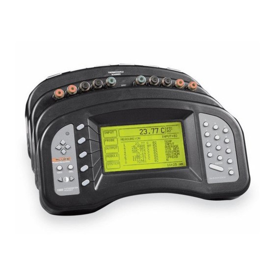
Sign In
Upload
Manuals
Brands
Fluke Manuals
Thermometer
1560 Black Stack
Fluke 1560 Black Stack Manuals
Manuals and User Guides for Fluke 1560 Black Stack. We have
1
Fluke 1560 Black Stack manual available for free PDF download: User Manual
Fluke 1560 Black Stack User Manual (187 pages)
Thermometer Readout
Brand:
Fluke
| Category:
Thermometer
| Size: 0.81 MB
Table of Contents
Table of Contents
3
1 Before You Start
13
Symbols Used
13
Table1 International Electrical Symbols
13
Safety Information
14
Warnings
14
Cautions
15
Authorized Service Centers
15
2 Introduction
17
Features
17
Figure 1 1560 Black Stack Thermometer with Two Modules Attached
17
Components
19
Base Microprocessor
19
Display
19
Figure 2 System Diagram
20
Figure 3 Typical Display
21
Figure 4 Typical Graph Mode Display
22
Buttons
23
Module Bus
24
Power Supply
24
Serial RS-232 Interface
24
Add-On Modules
25
Data Processing
26
Inputs
26
Sampling Control
26
Input Average
26
Temperature Conversion
26
Figure 5 Data Flow
27
Unit Conversion
28
Primary Measurement Display
28
Graph and Scroll Windows
28
Memory
28
Printer Outputs
28
Statistics
28
Output Routing
28
Display Data Fields
29
Data Output Channels
29
3 Specifications and Environmental Conditions
30
Specifications
30
Environmental Conditions
30
4 General Operation
31
Installing New Modules
31
Figure 6 Attaching New Modules
31
AC Power Source
33
Power on Self-Test
33
Adjusting the Screen Contrast
33
Making Measurements
33
Selecting Input Channels
33
Figure 7 Channel Numbering
34
Selecting the Probe Characterization
35
Measuring One Channel
36
Scanning Channels
36
Displaying Measurement Data
36
5 Soft-Key Functions
38
Input Menu
38
Measure
38
Primary Channel
40
Scan Channels
40
Scan Mode
41
Average
41
Probe Menu
42
Edit Probe
42
Conversion Types
43
R(Ω) Conversion
45
ITS-90 Conversion
45
W(T ) Conversion
46
IPTS-68 Conversion
46
Callendar-Van Dusen Conversion
47
RTD Polynomial Conversion
48
Thermistor T(R) Conversion
48
Thermistor R(T) Conversion
49
Thermocouple Volts Conversion
49
Standard Thermocouple Conversions
50
Thermocouple Table Conversion
51
Thermocouple Polynomial Conversion
52
Copy Probe
52
Test Conversion
54
Output Menu
54
Display Window Menu
55
Figure 8 Typical Statistical Display
55
Set Fields
55
Statistical Window
55
Graph Window
57
Table 4 CALCULATION Option
57
Clear Graph
58
Figure 9 Typical Graph Window Display
58
Scrolling Window
58
Figure 10 Typical Scrolling Display
59
Output Channel
59
Print Output
60
Print Memory
61
Clear Statistics
62
Module Menu
62
Set up Screen
62
Set up Device
63
Calibrate Device
64
Module Information
65
System Menu
66
Units
66
Password
67
Time
67
System Information
68
System Reset
69
6 Digital Communications Interface
71
Overview
71
Serial Interface
71
Figure 11 RS-232 Cable Wiring
71
Command Syntax
72
Command Summary
73
Commands
73
Measurement Data Commands
73
Calculate[N]:Average[N]:Clear
73
Command Summary
74
Command Summary Continued
75
Command Summary Continued
76
Command Summary Continued
77
Calculate[N]:Average[N]:Clear:all
78
Calculate[N]:Average[N]:Data
78
Calculate[N]:Average[N][:State]
79
Calculate[N]:Average[N]:Type
79
Configure[<Channel>]
79
Table 10 Statistical Calculation Types
79
Configure
80
Data[:Data]:Value? [Mem,]<Numeric_Value
80
Data:points? [MEM]
80
Fetch[:Temperature]? [<Channel>]
81
Measure[:Temperature]? [<Channel>]
81
Read[:Temperature]
81
Sense[N]:Average:data
82
Measurement Control Commands
82
Abort
82
Initiate[:Immediate]
82
Initiate:continuous
83
Initiate:continuous <Boolean
83
Sense:average:count <Numeric_Value
83
Table 11 Measurement Control Commands
83
Sense: Average[:State]
84
Sense:average:count
84
Sense:average[:State] <Boolean
84
Trigger[:Sequence]:Count
84
Trigger[:Sequence]:Count <Numeric_Value
84
Input Channel Commands
85
Trigger[:Sequence]:Delay
85
Trigger[:Sequence]:Delay <Numeric_Value
85
Trigger[:Sequence]:Timer
85
Trigger[:Sequence]:Timer <Numeric_Value
85
Route:close <Channel
86
Route:close:state
86
Route:primary
86
Table 12 Input Channel Commands
86
Route:scan:alternate
87
Route:scan:alternate <Boolean
87
Route:scan[:List]
87
Route:scan[:List] <Channel_List
87
Route:scan:state
88
Route:scan:state <Boolean
88
Probe Commands
89
Table 13 Probe Command Summary
89
Calculate[N]:Convert:catalog
90
Table 14 Conversion Type Mnemonics
90
Calculate[N]:Convert:copy <Channel
91
Calculate[N]:Convert:data
91
Calculate[N]:Convert:name <Conversion_Name
91
Table
92
Calculate[N]:Convert:name
93
Calculate[N]:Convert:parameter:catalog
93
Calculate[N]:Convert:parameter:value <Parameter_Name>, <Nu- Meric_Value>[,<Parameter_Name>,<Numeric_Value
93
Calculate[N]:Convert:parameter:value? <Parameter_Name
93
Calculate[N]:Convert:parameter:value? ALL
94
Calculate[N]:Convert:snumber <Serial_Number
94
Calculate[N]:Convert:snumber
94
Calculate[N]:Convert:srlow <Sub-Range_Number
94
Calculate[N]:Convert:srlow
94
Calculate[N]:Convert:srhigh <Sub-Range_Number
95
Calculate[N]:Convert:srhigh
95
Calculate[N]:Convert:test? <Numeric_Value>[,<Numeric_Value>]
95
Output Channel Commands
95
Output[N]:Calc <Numeric_Value
96
Output[N]:Calc
96
Table 16 Output Channel Commands
96
Output[N]:Nchannel <Channel
97
Output[N]:Nchannel
97
Output[N]:Pchannel <Channel
97
Table 17 Output Calculation Types
97
Output[N]:Pchannel
98
Output[N][:State] <Boolean
98
Output[N][:State]
98
Printer Commands
99
Hcopy:abort
99
Hcopy[:Immediate] <Printer_Number>,<Numeric_Value
99
Hcopy:printer[N][:State] <Boolean
99
Table 18 Printer Commands
99
Hcopy:printer[N][:State]
100
Communication Interface Commands
100
System:communicate:serial[:Receive]:Baud <Numeric_Value
100
System:communicate:serial[:Receive]:Baud
100
System:communicate:serial[:Receive]:Fduplex <Boolean
100
System:communicate:serial[:Receive]:Fdup
101
System:communicate:serial[:Receive]:Linefeed <Boolean
101
System:communicate:serial[:Receive]:Linefeed
101
Table 19 Communication Interface Commands
101
Module Commands
102
System:configure:cdevice
102
System:configure:communicate[N]:Daddress
102
Table 20 Module Commands
102
System:configure:communicate[N]:Maddress
103
System:configure:ichannel
103
System:configure:idevice
103
System:configure:input[N]:Daddress
103
System:configure:input[N]:Maddress
103
System:configure:mnumber
104
System:configure:module[N]:Device[N]:Information
104
System:configure:module[N]:Dnumber
104
System:configure:module[N]:Information
104
System:configure:ochannel
105
System:configure:odevice
105
System:configure:output[N]:Daddress
105
System:configure:output[N]:Maddress
105
System:configure:pdevice
105
System:configure:printer[N]:Daddress
106
System:configure: Printer[N]:Maddress
106
System:module[N]:Device[N]:Read? <Device_Command
106
System:module[N]:Device[N]:Write <Device_Command>,<Value
106
System Commands
107
Idn
107
Table 21 System Commands
107
Opt
108
Rst
108
System:date <Year>,<Month>,<Day
108
System:date
109
System:snumber <Serial_Number
109
System:snumber
109
System:time <Hour>,<Minute>,<Second
109
System:time
109
System:version
109
Unit:temperature <Unit
110
Unit:temperature
110
Status Commands
110
Cls
110
ESE <Numeric_Value
110
Ese
111
Esr
111
Opc
111
SRE <Numeric_Value
112
Table 22 Status Commands
112
Sre
113
Stb
113
Status:operation:condition
114
Status:operation:enable <Numeric_Value
114
Tst
114
Wai
114
Status:operation:enable
115
Status:operation[:Event]
115
Status:preset
115
Status:questionable:condition
115
Status:questionable:enable
116
Status:questionable:enable <Numeric_Value
116
Status:questionable[:Event]
116
Status:queue[:Next]
116
System:error
116
Programming Example
118
Figure 12 Programming Example
119
2560 /2567 SPRT Module
120
Description
120
Specifications
120
Operation
121
Connecting a Probe
121
Figure 13 Sensor Wiring Diagram
121
Setting Coefficients
122
Current
122
Device Setup Commands
122
Table 23 SPRT Module Device Commands
122
Calibration
123
Calibration Parameters
123
Front-Panel Access
123
Calibration Procedure (2560)
124
2561 HTPRT Module
126
Description
126
Specifications
126
Operation
127
Connecting a Probe
127
Figure 14 Sensor Wiring Diagram
127
Setting Coefficients
128
Current
128
Device Setup Commands
128
Table 24 HTPRT Module Device Commands
128
Calibration
129
Calibration Parameters
129
Front-Panel Access
129
Calibration Procedure
130
2562 /2568 PRT Scanner Module
131
Description
131
Specifications
131
Operation
132
Figure 15 PRT Scanner Module Sensor Wiring Detail
132
Connecting a Probe
133
Wire Configuration
133
Current
134
Device Setup Commands
134
Setting Coefficients
134
Calibration
135
Calibration Parameters
135
Table 25 PRT Scanner Commands
135
Front-Panel Access
136
Calibration Procedure (2562)
136
Calibration Procedure (2568)
137
2563 Thermistor Module
138
Description
138
Specifications
138
Operation
139
Connecting a Thermistor
139
Figure 16 Sensor Wiring Diagram
139
Setting Coefficients
140
Current
140
Device Setup Commands
140
Table 26 Thermistor Module Device Commands
140
Calibration
141
Calibration Parameters
141
Front-Panel Access
141
Calibration Procedure
142
2564 Thermistor Scanner Module
144
Description
144
Specifications
144
Operation
145
Wire Configuration
145
Connecting a Probe
145
Setting Coefficients
146
Figure 17 Thermistor Scanner Module Sensor Wiring Detail
146
Current
147
Device Setup Commands
147
Calibration
148
Calibration Parameters
148
Front-Panel Access
148
Table 27 Thermistor Scanner Module Commands
148
Calibration Procedure
149
2565 Precision Thermocouple Module
151
Description
151
Specifications
151
Calculating Accuracy
152
Operation
153
Connecting a Thermocouple
153
Selecting the Thermocouple Type
153
Selecting the CJC Type
153
Figure 18 2565 Module Thermocouple Receptacle Operation
154
Using Calibrated Thermocouples
155
Suggestions for Optimum Accuracy
155
Ambient Environment
155
Ground Currents
155
Thermal Settling
155
Warm-Up Time
155
Setup Parameters
156
Calibration
156
Calibration Parameters
156
Front-Panel Access
156
Table 28 Precision Thermocouple Module Calibration Parameters
156
Calibration Procedure
157
2566 Thermocouple Scanner Module
159
Description
159
Specifications
159
Calculating Accuracy
160
Operation
160
Connecting a Thermocouple
160
Selecting the Thermocouple Type
160
Selecting the CJC Type
161
Using Calibrated Thermocouples
161
Suggestions for Optimum Accuracy
162
Ambient Environment
162
Thermal Settling
162
Warm-Up Time
162
Setup Parameters
162
Calibration
162
Calibration Parameters
162
Front-Panel Access
163
Table
163
Calibration Procedure
164
3560 Extended Communication Module
166
Description
166
Specifications
166
Installation
166
GPIB Communication Device
166
Table 30 3560 Specifications
167
Capability
168
Connection
168
Device Setup
168
Commands
169
Device Clear
169
Device Setup Commands
169
Serial Poll
169
Serial Communication Device
170
Connection
170
Device Setup
170
Table 31 GPIB Communicatinos Device Commands
170
Commands
171
Device Setup Commands
171
Serial Printer Device
172
Device Setup
172
Table 32 Serial Communication Device Commands
172
Printing Measurement Data
173
Device Setup Commands
173
Parallel Printer Device
174
Connection
174
Device Setup
174
Table 33 Serial Printer Device Commands
174
Printing Measurement Data
175
Device Setup Commands
175
Table 34 Parallel Printer Device Commands
175
Analog Output Device
176
Connection
176
Device Setup
176
Selecting Data
177
Calibration
177
Device Setup Commands
178
Table 35 Analog Output Device Commands
178
15 Maintenance
179
16 Troubleshooting
180
Incorrect Temperature Reading
180
Incorrect Resistance or Voltage Reading
180
Communication Difficulties
181
Blank Screen
182
Error Message at Power up
182
CE Comments
182
EMC Directive
182
Emission Testing
183
Immunity Testing
183
Low Voltage Directive (Safety)
183
Advertisement
Advertisement
Related Products
Fluke Hart Scientific 1523
Fluke 1529 Chub-E4
Fluke 1595A
Fluke 1552A Ex
Fluke 1529
Fluke 1504
Fluke 1524-P4-256
Fluke Stik 1551A-9-DL
Fluke 1507
Fluke 150X Series
Fluke Categories
Measuring Instruments
Test Equipment
Multimeter
Thermometer
Laboratory Equipment
More Fluke Manuals
Login
Sign In
OR
Sign in with Facebook
Sign in with Google
Upload manual
Upload from disk
Upload from URL