
Related Manuals for Extraflame Lucrezia Steel


Summary of Contents for Extraflame Lucrezia Steel
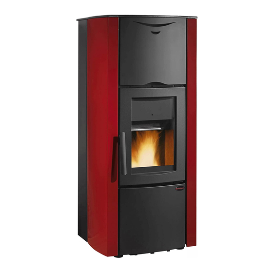
- Page 1 Stufe a Pellet Lucrezia Steel Lucrezia Idro Carefully read the instructions before installing, using and maintaining. The instructions book is an integral part of the product.
- Page 3 Congratulations! You are now the owner of an Extrafl ame stove! The Extrafl ame pellet stove is an ideal heating solution. It utilises the most advanced technology and is manufactured to the highest standards with a contemporary design, allowing you to enjoy the ambience and warmth of a natural fl ame in complete safety.
-
Page 5: Table Of Contents
Index Chapter 1 WARNINGS AND SAFETY DEVICES......................7 Chapter 2 WHAT IS THE PELLET? ..........................8 PELLET STORAGE ..................................8 PELLET FEEDING ..................................8 Chapter 3 SAFETY DEVICES ............................9 FLUE EXHAUST BREAKAGE ..............................9 PELLET FEED MOTOR BREAKAGE ............................9 NO IGNITION....................................9 TEMPORARY POWER CUT ..............................9 ELECTRIC SAFETY ..................................9 FLUE EXHAUST SAFETY DEVICE ............................9 PELLET TEMPERATURE SAFETY DEVICE ........................9... - Page 6 EXTERNAL THERMOSTAT FUNCTIONING IN STBY/TOFF MODE (TO ALSO BE USED FOR TELEPHONIC ACTUATOR) ..................................... 24 USE......................................24 IGNITION ....................................25 NORMAL FUNCTIONING ..............................26 SWITCH-OFF ................................... 26 Chapter 6 REMOTE CONTROL ..........................27 Chapter 7 WATER TEMPERATURE ADJUSTMENT ....................28 Chapter 8 USER PARAMETERS ..........................
-
Page 7: Warnings And Safety Devices
Chapter 1 WARNINGS AND SAFETY DEVICES The stoves produced by our establishment are built with manufacturer. attention to the individual components in a way to protect Do not pull, disconnect, twist electric cables leaving the both the user and the installer from any accidents. It is stove, even if disconnected from the electric power supply therefore recommended that after any intervention on the mains. -
Page 8: Chapter 2 What Is The Pellet
Chapter 2 WHAT IS THE PELLET? Pellets are realised by subjecting wood shavings i.e. the rejects of pure wood (without paint) sawmill, carpenter products and products from other activities connected to working and transforming wood, to very high pressures. This type of fuel is absolutely ecological as no glues are used to hold it together. In fact, the compactness of the pellets is guaranteed through time by a natural substance that is found in wood: lignin. -
Page 9: Chapter 3 Safety Devices
Chapter 3 Chapter 3 SAFETY DEVICES FLUE EXHAUST BREAKAGE If the suction device stops, the electronic board immediately blocks the pellet supply. PELLET FEED MOTOR BREAKAGE If the motor reducer stops, the stove continues to function until the minimum cooling level is reached. NO IGNITION If a fl ame is not developed during the ignition phase, the appliance automatically attempts ignition again, this time without pellet feeding. -
Page 10: Installation And Safety Devices
Chapter 3 INSTALLATION AND SAFETY DEVICES The installation, relative plant connections, commissioning and inspection of correct functioning must be carried out perfectly, in total compliance with Standards in force, both national and regional, as well as these instructions. For Italy, installation must be carried out by profesionally authorised staff (law dated 5 March 1990 n°46). Extrafl ame S.p.A. -
Page 11: Safety Devices For Closed Vessel Plant
Chapter 3 SAFETY DEVICES FOR CLOSED VESSEL PLANT According to the UNI 10412-2 (2006) Standard in force in Italy, the closed plants must have: Safety valve Pump control thermostat Acoustic alarm activation thermostat Temperature indicator Pressure indicator Acoustic alarm Adjustment automatic circuit breaker switch Automatic circuit breaker switch (block thermostat) Circulation system Expansion system... -
Page 12: Assembly And Installation Instructions
Chapter 4 ASSEMBLY AND INSTALLATION INSTRUCTIONS The installation must comply with: UNI 10683 (2005) heat generators fed with wood and other solid fuels: installation. The chimneys must comply with: UNI 9731 (1990) chimneys: classifi cation according to thermal resistance. EN 13384-1 (2006) calculation method of the thermal and fl uid-dynamic features of the chimney. UNI 7129 point 4.3.3 provisions, local rules and prescriptions of the fi re brigade. -
Page 13: Installation
Chapter 4 EXHAUST VENTING SYSTEM A system for fume exhaust venting that is independent from the appliance, composed of a pipe or channel, chimney or single fl ue, and chimney cap. FORCED DRAUGHT Air circulation by means of a fan driven by an electric motor. NATURAL DRAUGHT Draught resulting in a chimney/fl ue due to the diff erence in the volume mass existing between the (hot) fumes and the surrounding atmospheric air, without any mechanical suction aid installed inside or on top... -
Page 14: Connection To The Exhaust Venting System
Chapter 4 CONNECTION TO THE EXHAUST VENTING SYSTEM EXHAUST CHANNEL OR PIPE For the assembly of the exhaust channels it is imperative to use non-fl ammable materials that are resistant to combustion products and any condensates. It is forbidden to use fl exible metal pipes and asbestos cement for connecting the stove to the fl ue, also for pre- existing exhaust channels. -
Page 15: Chimney Or Single Flue
Chapter 4 the fl ue connection. It is forbidden to run other air feed channels or piping for utilities inside the exhaust channels, even if they are oversized. It is also forbidden to fi t manual draught adjustment devices on the forced draught appliance. - Page 16 Chapter 4 Windproof chimney cap < 3 m 3 - 5 % Flue Inspection Inspection fi gure 4.5 fi gure 4.6 < 3 m External insulated 45° duct Inspection 45° Inspection fi gure 4.7 fi gure 4.8 ASSEMBLY AND INSTALLATION INSTRUCTIONS...
-
Page 17: Connection To The Flue And Combustion Product Exhaust Venting
Chapter 4 CONNECTION TO THE FLUE AND COMBUSTION PRODUCT EXHAUST VENTING The fl ue must receive exhaust from a single heat generator. Direct discharge towards enclosed areas, even when roofl ess, is forbidden. Direct discharge of combustion products must take place on the roof and the exhaust duct must have the features set forth in the section “Chimney or single fl ue”. -
Page 18: Connection To External Air Intakes
If the combustion air is collected directly from the outside by means of a pipe, it is necessary to fit a downward bend or a wind hood on the outside. In addition, no grating or similar device should be positioned. (Extraflame S.p.A. suggests creating an air intake directly communicating with the installation room, even if air is collected from outside by means of a pipe). -
Page 19: Product Functionality
Chapter 5 Chapter 5 PRODUCT FUNCTIONALITY CONTROL BOARD REMOTE CONTROL SENSOR fi gure 5.1 ON/OFF BUTTON By pressing button 1 it is possible to switch the stove on and off automatically. AIR TEMPERATURE SETTING Buttons 2 and 3 are used to adjust the room temperature of water. FUNCTIONING POWER Buttons 4 and 5 adjust the heating power . -
Page 20: Mode
Chapter 5 Commands procedure Remove and restore the stove power supply using the master switch or using the power supply cable. The stove sequentially displays the following items before reaching “ OFF”: Versione Microprocessor version ( EXTRAH2O_2 or successive versions) Mode ( WINTER as set in the factory) Language ( LANGUAGE) Current day and time adjustment ( CLOCK) -
Page 21: Mode Selection
Chapter 5 ING1 connection input between clamps ING1 and COM of the terminal board ING2 connection input between clamps ING2 and COM of the terminal board ING1 priority over ING2 OUT3 and OUT4 are the supplementary board outputs controlled by the state of input ING1. The outputs status indicated in the table below are only to be considered valid with the pump working (stove water temperature >... -
Page 22: Winter Mode
Chapter 5 Commands procedure Remove and restore the stove power supply using the master switch or using the power supply cable. The stove sequentially displays the following items before reaching “ OFF”: Microprocessor version ( EXTRAH2O_2 or successive versions) Mode Selection ( WINTER as set in the factory) Language ( LANGUAGE) Current day and time adjustment ( CLOCK) Level ( LEVEL setting reserved for authorised technicians) -
Page 23: Winter Domestic Mode
Chapter 5 The stove works controlling the state of the priority input (ING1): when the thermostat results satisfi ed, the stove immediately switches off . State of input ING1: Closed contact or to be satisfi ed Contact open and satisfi ed (fl ashes t1 on display D2) State of input ING2: ignored The outputs status indicated in the table below are only to be considered valid with the stove water temperature higher than the anti-condensate threshold. -
Page 24: External Thermostat Functioning In Stby/Toff Mode (To Also Be Used For Telephonic Actuator)
Chapter 5 State of clamps State of outputs State of stove ING1 closed and ING2 closed OUT4 deactivated (0 V) Stove on OUT3 active (230 V, 50 Hz ) ING1 open and ING2 closed OUT4 active (230 V, 50 Hz ) Stove on OUT3 deactivated (0 V) ING1 external contact connected... -
Page 25: Ignition
Chapter 5 The stove you have purchased uses pellet fuel. This type of material is obtained from natural waste from the machining of wood. By means of a special process that does not require the use of any binding agent and additive, the waste is compressed in industrial machinery under high pressure and they become solid wooden pellets. -
Page 26: Normal Functioning
Chapter 5 NORMAL FUNCTIONING When ignition has taken place, the user can adjust the heating power using buttons 4 and 5. By pressing button 4 the heat power is decreased and therefore also the consumption of pellets per hour, vice versa by pressing 5 the heating power is increased and as a consequence also pellet consumption. -
Page 27: Remote Control
Chapter 6 Chapter 6 REMOTE CONTROL The heat setting, the temperature, and automatic start/stop of the stove can be remote controlled. S = Luminous warning light that indicates which keys have been pressed. Correspondence of display keys with remote control keys 1 = p3+p5 2 = p2... -
Page 28: Water Temperature Adjustment
Chapter 7 Chapter 7 WATER TEMPERATURE ADJUSTMENT The appliance can control the water temperature through a digital proble which automatically adjusts the machine functioning when nearing the desired temperature. When the stove is started and has entered normal functioning mode, display D1 will shows the water temperature. -
Page 29: User Parameters
Chapter 8 Chapter 8 USER PARAMETERS USER PARAMETERS WEEKLY PROGRAMMER Display D1 Display D2 Function UT 0 Act./Deact. Weekly programmer 00:00 UT 1 Time 1st switch-on 00:00 UT 2 Time 1st switch-off OFF 1 UT 3 Consents for 1st switch on/off for various days UT 4 Installer parameter 00:00... - Page 30 Chapter 8 Parameter Value Adjustment Confi rmation Function Keys Display D2 Display D1 UT 0 Act. /deact. weekly programmer 2 or 3 ON/OFF UT 1 Time 1st switch-on 2 or 3 OFF or from 00:00 to 23:50 UT 2 Time 1st switch-off 2 or 3 OFF or from 00:00 to 23:50 UT 3...
- Page 31 Chapter 8 To confi rm and continue programming, press button 5. Press button 4 to go back to the previous parameter. Parameter 4 (D2=4(fl ashing); D1= “00”) This parameter is reserved for the after-sales service and must not be modifi ed. Parameter 5 (D2=5(fl ashing);...
-
Page 32: Pellet Feed Adjustment
Chapter 8 Parameter A (D2=A(fl ashing); D1=Ex. “OFF 1”) At this point the values introduced in this parameter have no value as the ignition and switch-off of the 3rd time span have been disabled. To confi rm and continue programming, press button 5. Press button 4 to go back to the previous parameter. -
Page 33: Springs Automatic Cleaning Times
Chapter 8 Adjustment table Increase the percentage value by 5 points and try the stove with the new LACK OF calibration for at least half an hour. If the problem is attenuated, but not solved, FUEL increase by another 5 points. Repeat the operation until the problem is solved. If the problem cannot be resolved, contact the after-sales service. -
Page 34: Chapter 9 Cleaning
Chapter 9 Chapter 9 CLEANING Maintenance operations guarantee correct functioning of the product through time. Failure to comply with these operations can jeopardise the safety of the product. BRAZIER CLEANING Through a mechanical system, the cleaning of the brazier is carried out at pre-fi xed intervals, in automatic mode from the stove. -
Page 35: Door And Ash Drawers Gaskets
Chapter 9 DOOR AND ASH DRAWERS GASKETS The gaskets guarantee the tightness of the stove and its consequent good functioning. These must be checked regularly: if they should be worn or damages they must be replaced immediately. These operations must be carried out by an authorised technician. For correct functioning, the stove must undergo routine maintenance by an authorised technician, at least once a year. -
Page 36: Commissioning Operations
Chapter 10 Chapter 10 COMMISSIONING OPERATIONS MOUNTING THE TILES (ONLY LUCREZIA IDRO) The tiles mounting operations must be carried out by an authorised technician. Remove the 4 fi xing screws of the 2 cast iron sides as indicated in the drawing. Remove the 2 screws fi xing the upper grate. - Page 37 Chapter 10 Position the side tiles in the appropriate iron hooks, starting from the bottom upwards, in the two sides of the stove. (NB The side tiles are all the same!) Reposition the 2 cast iron sides and fi x with the 4 previously removed screws.
-
Page 38: Brazier Bracket
Chapter 10 BRAZIER BRACKET Before igniting the stove, make sure to have removed the bracket indicated in the fi gure. Remove the bracket Remove the screw fi gure 10.5 BRAZIER POSITIONING INSTRUCTIONS fi gure 10.6 The two pieces shown in the fi gure, which constitute the fuelling brazier, are placed inside the pellet tank. Before igniting, position them as illustrated. -
Page 39: Chapter 11 Product Display Tables
Chapter 11 PRODUCT DISPLAY TABLES SIGNALS SIGNALS REASON SOLUTION DISPLAY When the stove switches off (normal or caused by an alarm) it is A new ignition is attempted necessary to wait until it cools down completely and then clean when the stove has just the pot. - Page 40 Chapter 11 ALARMS SIGNALS REASON SOLUTION DISPLAY D1 It is on in the presence of one of the alarms described below and is accompanied by the relative signal in display D1, which identifi es the cause. To reset the alarm, just hold key 1 down for 3 Indicates the presence of an seconds when the stove is completely cold.
- Page 41 Chapter 11 Every time the stove displays one of the alarms listed above it will switch-off automatically. WAIT Attempt to release the alarm The stove will block any release attempt during this phase, FOR COOL. with stove still in cooling showing the alarm itself and WAIT FOR COOL alternately on the + ALARM mode.
- Page 42 Chapter 11 LUMINOUS INDICATORS SIGNALS REASON SOLUTION INDICATOR LIGHT It is on/off when the Weekly programmer function is active/deactivated. It indicates weekly For all settings relative to the following function see the “Weekly programmer functioning. programmer” function. It is on/off when the room temperature is below/above the set threshold. It indicates the Room To modify the temperature threshold, use keys 2 and 3 during normal thermostat function.
-
Page 43: Warranty Conditions
EXTRAFLAME S.p.A. is not liable for any damages that can, directly or indirectly, aff ect persons, objects and pets as a consequence of failure to comply with the prescriptions indicated in this manual/book. -
Page 44: Quality Contro
QUALITY CONTROL etichetta codice a barre QUALITY CONTROL... - Page 45 Notes...
- Page 46 Notes...
- Page 47 Notes...
- Page 48 Extrafl ame reserves the right to vary the features and data given in this document at any time without forewarning, in order to improve its products. This manual, therefore, cannot be considered as a contract for third parties. This document is available at www.extraflame.it/support 004275268 - INGLESE Manuale utente Lucrezia Idro - Lucrezia Steel REV 018 25.11.09...
Need help?
Do you have a question about the Lucrezia Steel and is the answer not in the manual?
Questions and answers