Extraflame comfort idro L80 User Manual
Hide thumbs
Also See for comfort idro L80:
- Instruction manual (52 pages) ,
- Instruction manual (72 pages) ,
- Instruction manual (84 pages)
Table of Contents
Advertisement
Quick Links
Download this manual
See also:
Instruction Manual
Advertisement
Table of Contents

Related Manuals for Extraflame comfort idro L80


Summary of Contents for Extraflame comfort idro L80
- Page 1 UseR MANUAl comfort IDro l80 MADE ITALY design & production 004276697 - rev 005 eNGlIsH/INGlese...
- Page 2 ENGLISH...
-
Page 3: Table Of Contents
INStaLLatIoN ........................................6 General ..................................................6 HyDrauLIc SyStEM ......................................8 InstallatIon and safety devIces ....................................... 8 aNtI-coNDENSatIoN DEVIcE (MaNDatory) ............................9 coMfort IDro L80 DEtaILS ..................................10 safety latch and extractIon of the Insert..................................11 fEaturES........................................12 rearM...................................................12 fuse ....................................................12 coMfort INSErt IDro L80 INStaLLatIoN............................... 13 MInIMuM clearance ............................................13... -
Page 4: English
We thank you for having chosen our company; our product is a great heating solution developed from the most advanced technology with top quality machining and modern design, aimed at making you enjoy the fantastic sensation that the heat of a flame gives, in complete safety. Warnings This instructions manual is an integral part of the product: make sure that it always accompanies the appliance, even if transferred to another owner or user, or if transferred to another place. -
Page 5: Routine Maintenance
Š DO NOT LEAVE THE PACKAGING ELEMENTS WITHIN REACH OF CHILDREN OR UNASSISTED DISABLED PERSONS. Š THE HEARTH DOOR MUST ALWAYS BE CLOSED DURING NORMAL FUNCTIONING OF THE PRODUCT. Š WHEN THE APPLIANCE IS FUNCTIONING AND HOT TO THE TOUCH, ESPECIALLY ALL EXTERNAL SURFACES, ATTENTION MUST BE PAID Š... -
Page 6: Installation
InstallatIon general The flue gas exhaust and hydraulic connections must be carried out by qualified personnel who must issue installation conformity documentation compliant with national standards. the installer must provide the owner or person acting for him, according to the legislation in force, with the declaration of conformity, supplied with: 1) the use and maintenance manual of the appliance and of the system components (such as for example, the smoke ducts, chimney, etc.);... - Page 7 In the presence of type B gas appliances with intermittent operation not intended for heating, they must have their own aeration and/or ventilation opening. The air inlets must meet the following requirements: Š they must be protected with grids, metal mesh, etc., but without reducing the net useful section; Š...
-
Page 8: Hydraulic System
HYDRAULIC SYSTEM Certain concepts referring to the Italian Standard UNI 10412-2 (2009) are described in this chapter. As previously described, when installing, all national, regional, provincial and council Standards in force provided by the country in which the appliance has been installed must be complied with. During installation of the generator it is MANDATORY to adjust the system with a manometer in order to display the water pressure. -
Page 9: Anti-Condensation Device (Mandatory)
DISTAnCES of SAfETY DEvICES ACCoRDIng To THE STAnDARD The temperature safety sensors must be in place on the machine at a distance no greater than 30 cm from the flow connection. Whenever the generators lack a device, those missing can be installed on the generator flow pipe, within a distance no greater than 1 m from the machine. CoMMISSIonIng CHECkS Before connecting the boiler: a) wash all system piping thoroughly in order to remove any residues which might compromise the correct functioning of certain system... -
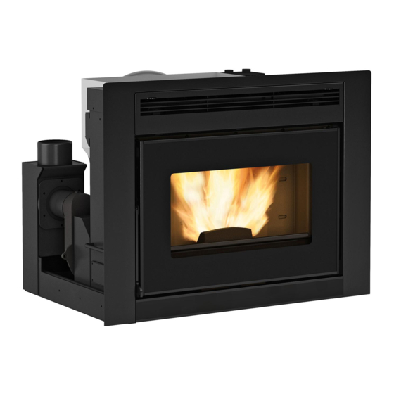
Page 10: Comfort Idro L80 Details
Comfort IDro l80 DetaIls Room air outlet Air vent Room air outlet System draining/filling Door handle Rocker with emergency card Fumes exhaust Pellet hopper Power supply 220v Fumes exhaust Power supply Combustive air 220v input Poker (x2) HyDraulIC InstallatIon 3 bar safety drain... -
Page 11: Safety Latch And Extraction Of The Insert
safety latCH anD extraCtIon of tHe Insert Use the poker supplied to perform the release/block operation. Holes present on two sides for the extraction of the insert via pokers. Extraction of the insert allows both to load the pellet inside the hopper and to perform routine maintenance (cleaning the ash pipe at year end) or extraordinary (replacement of... -
Page 12: Features
features Water content of the thermo-product heat exchanger (l) 14.6 volume of expansion vessel integrated into thermo-product (l) 3 bar safety valve integrated into the thermo-product Minimum and maximum pressure switch integrated into the thermo-product Pump integrated into the thermo-product Pump max. -
Page 13: Comfort Insert Idro L80 Installation
Insert preparatIon and InstallatIon, see attached fIle "Insert preparatIon and assembly" Comfort Insert Idro L80 InstALLAtIon The insert is supplied with a sliding base in iron that allows it to be installed in a pre-existing chimney. This sliding base allows the insert to be removed easily to load the pellets inside the hopper and for any maintenance or cleaning at the end of the season. -
Page 14: Fresh Air Ducts
fresh AIr duCts For correct operation, air must be allowed to recirculate inside the structure that covers the insert in order to prevent the appliance from overheating. To guarantee this, just realise one or more openings in the lower and upper part of the covering. The following measurements must be respected: Lower part (cold air inlet) with total minimum surface 550 cm². - Page 15 A hole must be made on the chimney support base (figure 1) for the recirculation of air and to guarantee the combustion air necessary for correct combustion of the insert. See "Air re-circulation pipes" chapter 227.2 Air inlet Base 210.5 (figure 1) If it is not possible to make a hole on the chimney support (figure 1), it is mandatory to realise two lateral holes (figure 2) ion the structure to guarantee the combustion air necessary for correct combustion of the insert.
-
Page 16: Assembly With Pedestal (Optional)
874.4 (figure 3) To safeguard from any overheating, the Comfort idro L80 is supplied with a probe that analyses the temperature inside the structure and intervenes by reducing the functioning power. thIs ventILAtIon system Is totALLy Independent from the AIr InLet for ComBustIon!! - Page 17 CoverIng ALreAdy exIstent If the insert is introduced inside an existing covering, proceed as described below. Š If necessary, create a lateral opening in the covering in a way to be able to access the flexible pipes at the height of the collar clamps. Š...
-
Page 18: Pellets And Feeding
Pellets and feeding Pellets are made by applying high pressure to sawdust, or wood waste products (not containing paint) from sawmills, carpentry and other activities related to processing and working with wood. Given that it does not use any glue to hold it together this type of fuel is completely environmentally friendly. -
Page 19: Radio/Emergency Card
Radio/emeRgency caRd The stove is fitted with an emergency radio card located under the rocker, which allows the basic operation of the stove in the event the LCD handheld remote is damaged or malfunctions. The functions that can be managed from the emergency card are: P1: On/off stove. -
Page 20: Handheld
handheld cOnFIGUratIOn HAndHeld codIng procedure: 1. disconnect the power supply to the stove. 2. press keys at the same time until the unIT selection screen appears. 3. using keys select the new unIT. 4. power the stove. confirm the selected unit within 10 seconds (all leds flash on the radio/emergency card) by pressing the oK key on the handheld. -
Page 21: Handheld Features
handheld FeatUreS The handheld is fitted with an lcd backlit display. The display remains lit for 5 seconds. After a certain period of time, in order to minimise battery consumption, the display turns off (sleep mode). It turns on again after pressing the on/oFF key (6). warnInG! do not place the handheld in direct or indirect contact with water. -
Page 22: Display
dISplay sCreen wiTh VenTilaTiOn nOT enaBled Stby active chrono active Battery low power 1-5^ Time Water temperature (H2o) detected in the boiler Set H2o temperature set Text display sCreen wiTh VenTilaTiOn enaBled Stby active chrono active Battery low power 1-5^ Time Water temperature (H2o) Temperature detected in... -
Page 23: General Menu
General menU FUnCTiOn FUnCTiOn Scroll parameters Back - exit key modify settings on - off key Access menu key poWer AmBIenT Temp. H2o Temp. VenTIlATIon SeT cHrono enABle cHrono eASy SeTup SeT prg 1 SeT prg 2 SeT prg 3 SeTTIngS dATe/TIme SeT prg 4... -
Page 24: Commissioning Settings
cOmmISSIOnInG SettInGS once the supply cable has been connected to the back of the generator, and after the insert has been locked with the latch, proceed with the configuration. lIne FreqUency 50/ 60hz If the generator is installed in a country with a frequency of 60Hz, the generator will display "incorrect line frequency". In this case, adjust the frequency to 60Hz. -
Page 25: Operation And Logic
OperatIOn and lOGIc once the previously listed points have been checked, press key for three seconds to ignite the stove. 15 minutes are available for the ignition phase. After ignition and after reaching the control temperature, the stove interrupts the ignition phase and switches to prepArATIon. preparatIOn during the preparation phase, the stove stabilises combustion, increasing it progressively, to then start ventilation and switch to WorK. -
Page 26: Set
pOwer The menu allows the generator power to be set minimum power 1, maximum power 5. To set: oK > Set > Power. rOOm temperatUre The menu allows to set the room temperature to reach. (front ventilation must be active). range: oFF - 07 - 40°c. -
Page 27: Set Chrono
Set chrOnO This function allows the generator's ignition and switch-off to be automatically programmed. By factory default, the SeT cHrono is disabled. The chrono allows the programming of 4 time slots within a day, which can be used every day of the week. Ignition and switch-off times can be set for each time slot, along with the specific days of application for the programmed time slot and the desired temperature. -
Page 28: Settings
SettInGS date/tIme Š lanGUaGe See cHApTer: commISSIonIng SeTTIngS. Š Set deGreeS Š dISplay The "dISplAy" menu allows: Š Set the timer to turn off the display Š regulation of display contrast backlight. Š Activation/deactivation of backlight. Š Set the timer to turn off the display (sleep Š... -
Page 29: Reset
reSet Allows the user to reset all modifiable values to the default values. To set: oK > SettingS > reSet. addItIOnal FUnctIOnS If conveyor accessories of the manufacturer are used , the connection must be made by a qualified technician. contact the dealer for further details lcd handheld remOte rOOm prOBe calIBratIOn This mode allows calibration of the room temperature detected by the lcd handheld remote (with ventilation active only). -
Page 30: Cleaning And Maintenance
TO FIND OUT WHERE YOUR NEAREST SERVICE CENTRE IS, CONTACT YOUR DEALER OR GO TO THE WEBSITE: WWW.LANORDICA-EXTRAFLAME.COM Cleaning and maintenanCe Follow the instruCtions always in Complete saFety! Š Make sure that the power supply cable plug is disconnected, since the generator could be programmed to switch-on. - Page 31 every day burn pot and Combustion Chamber: Suck up the residues present in the burn pot Remove the burn pot completely from the relevant compartment; Suck up the ash from the burn pot seat and combustion chamber. Release all holes present in the burn pot using the poker supplied.
-
Page 32: Routine Maintenance Performed By Qualified Technicians
QualiFied person, so as to avoid all risks. TO FIND OUT WHERE YOUR NEAREST SERVICE CENTRE IS, CONTACT YOUR DEALER OR GO TO THE WEBSITE: WWW.LANORDICA-EXTRAFLAME.COM routine maintenanCe perFormed by QualiFied teChniCians routine maintenance must be performed at least once a year. - Page 33 routine maintenanCe THE IMAGES ARE ILLUSTRATIONS ONLY. Fumes motor (disassembly and cleaning and fumes and "T" pipes), new silicone in the points envisioned Gaskets, inspections, door (replace and apply silicone where envisioned), burn pot and heat exchanger Combustion chamber and heat exchanger (full cleaning) including ignition-plug pipe Hopper (complete emptying and cleaning).
-
Page 34: Displays
Take the stove to OFFconditions using key 1 and repeat the procedure No current during the ignition phase. black ouT described in the "Ignition" chapter. * on models with this function. TO FIND OUT WHERE YOUR NEAREST SERVICE CENTRE IS, CONTACT YOUR DEALER OR GO TO THE WEBSITE WWW.LANORDICA-EXTRAFLAME.COM ENGLISH... - Page 35 Other restoration operations must be performed by an authorised The flue exhaust pipe is blocked technician. incorrect installation * on models with this function. TO FIND OUT WHERE YOUR NEAREST SERVICE CENTRE IS, CONTACT YOUR DEALER OR GO TO THE WEBSITE WWW.LANORDICA-EXTRAFLAME.COM ENGLISH...
-
Page 36: Guarantee Terms
Extraflame S.p.A. cannot be held liable for injury or damage which may - either directly or indirectly - be caused to persons, animals and property ensuing from failure to observe all the instructions provided in the relevant instruction manual and the warnings regarding installation, use and maintenance of the product, that can also be downloaded on the website. - Page 37 AddITIONAL wARNINGs Š Only use the fuel recommended by the manufacturer. The product must not be used as an incinerator. Š Do not use the product as a ladder or supporting structure. Š Do not place laundry on the product to dry it. Any clothes-horse or similar objects must be kept at due distance from the product. Danger of fire or damage to the coating.
- Page 38 ENGLISH...
- Page 39 ENGLISH...
- Page 40 The manufacturer reserves the right to vary the characteristics and the data reported in this pamphlet at any moment and without notice, in order to improve its products. This manual, therefore, cannot be regarded as a contract towards other parties. 31/01/2017 004276697- MAN_UT. COMFORT IDRO L80 - 005...
Need help?
Do you have a question about the comfort idro L80 and is the answer not in the manual?
Questions and answers