Extraflame Comfort P70 User Manual
Hide thumbs
Also See for Comfort P70:
- Instruction manual (84 pages) ,
- Assembly instructions manual (6 pages)
Table of Contents

Related Manuals for Extraflame Comfort P70


Summary of Contents for Extraflame Comfort P70
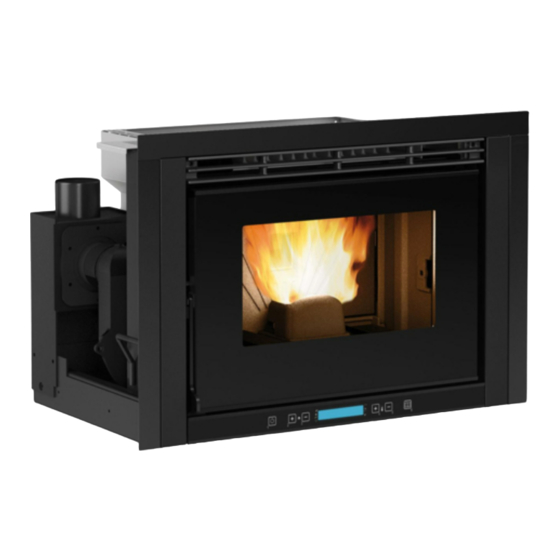
- Page 1 Comfort P70 & P70 h49 insert User mAnUAL engLish/ingLese...
-
Page 3: Table Of Contents
...............................................11 chimney caps ............................................11 Fumes eXhaust system product requirements ..............................12 combustion products outlet quota ..................................12 technical installation documentation ................................13 coMfort P70/ P70H49 inStaLLation ..........................14 minimum dimensions .........................................14 air circuLation PiPeS ................................15 assembly with slidinG base ......................................17 PedeStaL aSSeMbLy (oPtionaL): ............................17 MountinG tHe fraMeS ................................18... -
Page 4: English
Extraflame s.p.a. cannot be held responsible for the failure to comply with such precautions. After removing the packaging, ensure that the content is intact and complete. Otherwise, contact the dealer where the appliance was purchased. -
Page 5: Safety Devices
| eNgliSH Safety deviceS teRMS aNd defiNitiONS aeration: Air renewal is required both for the disposal of Safety deviceS the combustion products, and to prevent mixtures with a hazardous content of non-combusted gases. Key: * = present, - = not present closed hearth appliance: Appliance designed for operation with closed combustion chamber. -
Page 6: General
| eNgliSH fUNctiONal OPeRatiONS diagRaM state of the art installation and proper system operation include a series of activities: 1. Preliminary activities: Š verification of the suitability of the installation site, Š verification of the suitability of the fumes exhaust system, Š... -
Page 7: Installation
| eNgliSH iNStallatiON Installation in premises with fire hazards is forbidden. Installation in residential premises (except for sealed operation appliances) is also forbidden: Š in which there are liquid fuel-operated appliances with continuous or intermittent operation, which draw the combustion air in the room in which they are installed, or Š... -
Page 8: Fumes Exhaust System
| eNgliSH veNtilatiON aNd aeRatiON Of tHe iNStallatiON PReMiSeS Ventilation is deemed sufficient when the room is equipped with air inlets according to the table: air inlet see figure 2 Percentage of the net opening section with Minimum net opening value of Appliance categories Reference standard respect to the appliance fumes... -
Page 9: Smoke Duct
| eNgliSH Š nominal diameter; Š distance from combustible materials, indicated in millimetres, followed by the arrow and flame symbol; Š installer data and date of installation. every time one must cross combustible materials, the following indications must be complied with: SyMbOl deScRiPtiON qUOta[MM]... - Page 10 | eNgliSH Š counter-slope sections are not allowed; Š the smoke ducts must have, along their entire length, a diameter that is no less than that of the attachment of the appliance exhaust pipe; any section changes are allowed only on the inlet to the chimney; Š...
-
Page 11: Chimney
| eNgliSH exaMPleS Of cORRect cONNectiON tO tHe cHiMNey protection from rain protection from rain and wind and wind steel plate, airtight Max 3 mt 3 - 5% Insulated "t" fitting with inspection plug "t" fitting with "t" fitting with inspection plug inspection plug... -
Page 12: Fumes Exhaust System Product Requirements
| eNgliSH cOMbUStiON PROdUctS OUtlet qUOta the outlet quota is determined by measuring the minimum height between the roof covering and the lower point of the fumes expulsion section into the atmosphere; this quota must be outside the reflux area and at an adequate distance from obstacles which hinder or make the expulsion of the combustion products difficult or from openings or accessible areas. -
Page 13: Technical Installation Documentation
| eNgliSH coverings and finishings the coverings and finishings must only be applied after having verified the proper operation of the appliance according to the indicated modalities tecHNical iNStallatiON dOcUMeNtatiON When installation is complete, the installer must provide the owner or person acting for him, according to the legislation in force, with the declaration of conformity, supplied with: 1) the use and maintenance manual of the appliance and of the system components (such as for example, the smoke ducts, chimney, etc.);... -
Page 14: Comfort P70/ P70H49 Installation
| ENGLISH COMFORT P70/ P70H49 INSTALLATION The insert is supplied with a sliding metal base that allows it to be installed in a pre-existing flue. The sliding base allows the easy extraction of the insert both for feeding pellets into the feed-box and for any maintenance or cleaning at the end of the season. -
Page 15: Air Circulation Pipes
| ENGLISH AIR CIRCuLATION PIPES Create air recirculation inside the structure that covers the insert for correct operation. This prevents the appliance from over- heating. To guarantee this, just make one or more openings in the lower and upper parts of the covering. The following measurements must be respected: Š... - Page 16 5 cm (figure 3) To protect from any over-heating, the Comfort P70 and P70h49 is supplied with a probe that analyses the temperature inside the structure and intervenes by reducing the functioning power. THIS vENTILATION SySTEM IS TOTALLy INdEPENdENT FROM THE AIR INTAkE FOR COMBuSTION!!
-
Page 17: Assembly With Sliding Base
| ENGLISH ASSEMBLy wITH SLIdING BASE Take the sliding base and position it in the pre-existing flue. Use chalk to mark the blocking holes of the base on the flue surface. Drill 8 mm holes for the steel expansion inserts. Make a hole measuring 60 mm in line with the air intake. -
Page 18: Mounting The Frames
| ENGLISH MOuNTING THE FRAMES As standard, the insert has a finishing frame that, as well as finishing, covers the side slot required between the structure and covering. P70 uPPer frame assembly: Simply fit the frame on the relevant pins, as shown in figure 1. figure 1 P70h49 uPPer frame assembly: The upper frame is fitted via 2 screws as shown in figure 2. -
Page 19: Removing The Insert And Loading Pellets
| ENGLISH INSERT LOCkING ANd RELEASING SAFETy dEvICE open the door and turn, using the poker supplied, insert the lockbolt in the corner at the bottom on the left and turn anticlockwise to open (release) or clockwise to close (lock). OPEN - RELEASEd CLOSEd - LOCkEd To understand whether the insert is attached to the base properly, connect the plug to the socket and make sure it works with... -
Page 20: Pellets
Š Ö-NORM M 7135 Š dIN PLuS 51731 Extraflame recommends using pellets with a diameter of 6mm with its products. THE uSE OF POOR quALITy PELLETS OR ANy OTHER MATERIAL dAMAGES THE FuNCTIONS OF yOuR STOvE ANd CAN vOId THE wARRANTy ANd THE ANNExEd RESPONSIBILITy OF THE MANuFACTuRER. -
Page 21: Control Panel
| enGlisH Control panel OperaTION pOWer DISplaY OF varIOUS TemperaTUre TO aCCeSS aDJUSTmeNT TexT meSSageS SeTTINg THe meNU BUTTON ON/OFF Display iCons key Indicates the receipt of the radio signal It indicates weekly programming functioning On = during radio communication Indicator on = weekly programming active Off = no radio communication Indicator off = weekly programming disabled... -
Page 22: General Menu
| enGlisH General menu Go baCk - exit parameter sCrollinG: next (2) ; previous (3) 22.5°C 14:10 moDiFy settinGs Data: inCrease (4); DeCrease (5) ConFirm - aCCess menu set CloCk CHrono settinG enable CHrono ConFirm lanGuaGe it,en,Fr,De,es start prG1 Hours WitH key 6 user Display... -
Page 23: The Remote Control
| enGlisH tHe remote Control all that can normally be implemented through the lCD can be adjusted using the remote control. The table below provides a detailed description of the various functions: on / oFF pressing the key for three seconds, the stove will switch on or off poWer inCrease pressing the key will increase the operating power poWer DeCrease... -
Page 24: Commissioning Settings
| enGlisH CommissioninG settinGs Once the power cable at the back of the stove has been connected, move the switch, also located on the back, to (I). The switch at the back of the stove powers the stove board. The stove remains off and a first screen appears on the panel reading OFF. -
Page 25: Operation And Logic
| enGlisH operation anD loGiC 22.5°C 14:10 iGnition Once the points listed previously have been checked, press key 1 for three seconds to ignite the stove. 15 minutes are given for the ignition stage, after ignition and once the control temperature has been reached, the stove interrupts the ignition phase and switches to the STarT-Up mode. -
Page 26: Additional Thermostat (Optional)
| enGlisH aDDitional tHermostat (optional) The appliance can control the room temperature using an additional external thermostat (optional). after ignition (pressing key 1 or via chrono mode), the stove will work to reach the setting set on the thermostat, displaying (contact closed). -
Page 27: V1- Air
| enGlisH NO FUel: Š the stove can never develop a suitable flame, tending to remain very low even at high powers. Š at minimum power the stove tends to almost switch-off taking the stove into “ ” alarm condition. no pellets Š... -
Page 28: Keys Locked
| enGlisH STBY FUNCTION SeT aT OFF (DeFaUlT SeTTINg) If the Stby function is not active (OFF), if the stove reaches the set room temperature, it will go to minimum, modulating and displaying modulate. When the room temperature is below the setting, it will start to work again at the set power and displaying work. -
Page 29: V2 - Air
| enGlisH v2 - air - not useD The menu allows to adjust the speed of the ducted fan in percentage. CONTrOlS prOCeDUre press key 6 and set CloCk will appear. Š press key 2 several times until user is displayed. Š... -
Page 30: Programming Example
| enGlisH proGramminG example let's suppose that the weekly programmer function is to be used and 4 time slots are to be used in the following way: 1st time slot: from 08:00 to 12:00 every day of the week, with room temperature at 19°C, excluding saturday and sunday 2nd time slot: from 15:00 to 22:00 only on saturday and sunday, with room temperature setting of 21°C 1ST TIme SlOT SWITCH-OFF CONTrOlS prOCeDUre:... -
Page 31: Cleaning Under User's Responsibility
| ENGLISH CLEaNING uNdEr uSEr'S rESpoNSIbILIty The images are for illustration purposes. daILy burn pot: Remove the burn pot from the relevant compartment and free the holes using the special poker supplied, remove the ash from the burn pot using a vacuum cleaner. Vacuum the ash deposited in the brazier compartment. - Page 32 | ENGLISH CLEaNING uNdEr uSEr'S rESpoNSIbILIty The images are for illustration purposes. MoNtHLy Cleaning the heat exchanger: The heat exchangers chamber must be cleaned every month as the soot deposited on the rear of the cast iron hearth wall blocks the regular flow of fumes.
-
Page 33: Routine Maintenance
| ENGLISH routINE MaINtENaNCE In order to guarantee proper functioning and safety of the device, the operations indicated below must be performed every season or more often when necessary. door, aSH draWEr aNd burN pot GaSKEtS The gaskets ensure the tightness of the stove and its consequent proper operation. They must be checked periodically: in the event they are worn or damaged they must be replaced immediately. -
Page 34: Displays
| englisH Displays Display Reason Stove off staRt The start phase is in progress pellet feeDing Pellet feeding during the ignition phase is in progress ignition The ignition phase is in progress staRt-up The start phase is in progress WoRk The normal work phase is in progress MoDulation The stove is modulating... -
Page 35: Alarms
| englisH alaRMs Display explanation solution on and flashing: indicates the presence of an alarm The fixed triangle on the display and The alarm can be reset by pressing button 3 for 3 seconds only if key 1 flashing slowly indicate the the fumes motor has stopped and if 15 minutes have elapsed from presence of an alarm. -
Page 36: Warranty Conditions
Š EXTRAFLAME S.p.A. is not liable for any damage that can, directly or indirectly, affect persons, objects and pets as a consequence of failure to comply with the prescriptions indicated in this manual/book. - Page 37 Š Parts made of refractory material Š Masonry work Š The system particulars for the production of domestic hot water not supplied by EXTRAFLAME S.p.A. (water products only). Š The heat exchanger is excluded from the warranty unless an adequate anti-condensate circuit which guarantees a minimum return temperature of the appliance of at least 55°C (only water products).
- Page 40 www.lanordica-extraflame.com Extraflame reserves the right to vary the features and data shown in this booklet at any time and without prior notice, in order to improve its products. This manual cannot be considered as a contract for third parties.
Need help?
Do you have a question about the Comfort P70 and is the answer not in the manual?
Questions and answers