CODELOCKS CL400 Installation Instructions Manual
Hide thumbs
Also See for CL400:
- Installation instructions manual (10 pages) ,
- Instructions manual (7 pages) ,
- Instructions manual (7 pages)
Advertisement
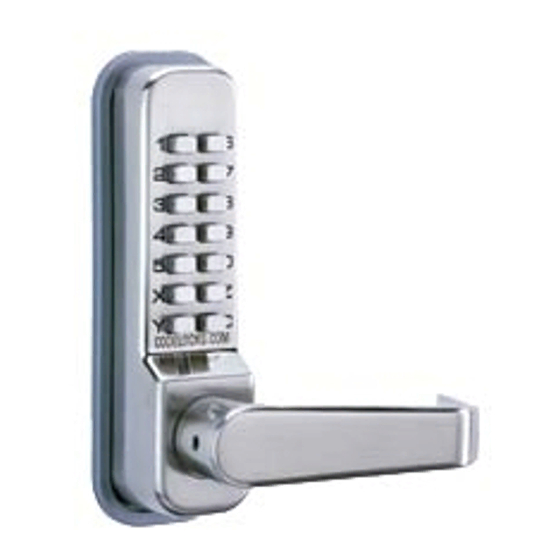
CL400 Installation Instructions
Contents
1 Front plate and handle
2 Back plate and handle
3 Neoprene seals x 2
4 Spindles a) RED & BLUE tipped spindles
b) Butterfly spindle
5 Fixing bolts x 3 (1x spare)
6 Spare code tumblers x 2
7 Tweezers (for changing the code)
8 Allen Key
9 Euro-profile cylinder escutcheons
1
Mortice latch, strike & 4 screws
0
1
2 bolt mortice lock and strike, with Allen
1
key
1
Double Europrofile cylinder & 3 keys
2
1
Latch support post
3
Installation template
Code change instructions
Code card
Tools Required:
• Power drill
Model
Model
410/415
420/425
• Drill bits 8mm, 16mm, 20mm, 25mm
• Phillips screwdriver
• Chisels 22mm and 25mm
• Hammer/mallet
• Stanley knife
• Adhesive tape
• Pencil
• Bradawl
• Tape measure
-
One pair
-
-
-
-
Page 1
Find more online at www.codelockssupport.com
Advertisement
Table of Contents

Subscribe to Our Youtube Channel
Related Manuals for CODELOCKS CL400


Summary of Contents for CODELOCKS CL400
- Page 1 Find more online at www.codelockssupport.com CL400 Installation Instructions Tools Required: Contents • Power drill Model Model 410/415 420/425 • Drill bits 8mm, 16mm, 20mm, 25mm 1 Front plate and handle • Phillips screwdriver 2 Back plate and handle • Chisels 22mm and 25mm •...
- Page 2 Find more online at www.codelockssupport.com Page 2...
- Page 3 Find more online at www.codelockssupport.com Check Operation of the Coded Front Plate On models 415 and 425 a free passage function is available. This is signified by a black dot on the ‘Y’ button. In normal operation the code needs to be entered every time to turn the lever. To put the lock into free passage mode first enter the code on the code card followed by the ‘Y’...
- Page 4 Find more online at www.codelockssupport.com STEP 9 Fit latch support post into back of the code side front plate according to the hand of your door, A for a right hand door, or B for a left hand door (see diagram). STEP 10 Cut two of the back socket head bolts to the required length for your door.
- Page 5 Find more online at www.codelockssupport.com Model 420/425 Installation Instructions STEP 4 Model 420/425 is a complete locking unit with all the parts necessary Fold the template accurately along the dotted line and tape it to the for a new installation, or the total replacement of an existing lock. door face with the top in line with the height line, and the fold on the door edge.
- Page 6 Find more online at www.codelockssupport.com STEP 11 Fix the two plates together using the socket head bolts, starting with the top fixing. Ensure that the two plates are truly vertical and then tighten the bolts. Do not use excessive force. STEP 12 Before closing the door, enter the code and check that the latchbolt will retract when the lever handle is depressed.
- Page 7 CODELOCKS UK HEADQUARTERS CODELOCKS INC US CODELOCKS (Australia) PTY LTD Tel: +44 (0) 1635 239645 Tel: +1 714 979 2900 Tel: +61 2 9882 1009 Fax: +44 (0) 1635 239644...
Need help?
Do you have a question about the CL400 and is the answer not in the manual?
Questions and answers