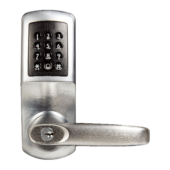
CODELOCKS CL5500 SERIES Installation Instructions Manual
Hide thumbs
Also See for CL5500 SERIES:
- Programming and operating instructions (13 pages) ,
- Installation instructions manual (14 pages) ,
- Getting started (4 pages)
Table of Contents
Advertisement
Quick Links
Advertisement
Table of Contents

Summary of Contents for CODELOCKS CL5500 SERIES
- Page 1 10/23/2018 KA-01201 · Customer Self-Service Home (/) > Knowledge Base - Home (/knowledgebase/) > KA-01201 Print CL5500 - US Version Installation Instructions Views: 82 Box Contents Check the contents of the box are correct https://support.codelocks.com/knowledgebase/article/KA-01201/en-us...
- Page 2 10/23/2018 KA-01201 · Customer Self-Service FUNCTIONS https://support.codelocks.com/knowledgebase/article/KA-01201/en-us...
- Page 3 N.B. When the Master Code is entered 3 times consecutively without performing a programming function, a penalty time of 10 seconds is activated. Disconnect the cables. SPECIAL FIXING NOTE REMOTE RELEASE OPTION Cables are provided for the REM 1 and REM 2 terminals on the circuit board. https://support.codelocks.com/knowledgebase/article/KA-01201/en-us...
- Page 4 Mark the holes to be drilled. Mark the centre line of latch on to the door edge. Apply the template to the other side of the door precisely against the height line and the centre line of latch mark. Mark the holes to be drilled again. (See diagram A). https://support.codelocks.com/knowledgebase/article/KA-01201/en-us...
- Page 5 5. Re-insert the latch and fix the screws, with the bevel towards the door frame. (See diagram B). 6. Fit the latch support post on the inside of the front plate, in outer hole side A for a left hand hung door and in outer hole B for a right hand hung door. (See diagram C). https://support.codelocks.com/knowledgebase/article/KA-01201/en-us...
- Page 6 Place the fixing plate over the cable tube and spindle. Screw the ring nut onto the cable tube until finger tight. Fit the alignment insert over the spindle. Screw the fixing bolts through to the front plate. (See diagram D) https://support.codelocks.com/knowledgebase/article/KA-01201/en-us...
- Page 7 ‘play’. When satisfied, draw around the outline of the strike plate, remove it and cut a rebate to enable the strike plate to lie flush with the surface. Re-fix the strike plate using both screws. https://support.codelocks.com/knowledgebase/article/KA-01201/en-us...
- Page 8 INSTALLATION OF CL5510PK 1. The position of the Codelocks CL5510 front unit on the door is determined by the position of the panic device. 2. Mark the position of the spindle hole for the panic device on both sides of the door.


Need help?
Do you have a question about the CL5500 SERIES and is the answer not in the manual?
Questions and answers