Table of Contents
Advertisement
Quick Links
Advertisement
Table of Contents

Related Manuals for GeoVision GV-Mobile NVR System


Summary of Contents for GeoVision GV-Mobile NVR System
- Page 1 GV-Mobile NVR System User’s Manual User’s Manual MBNVR-UM-A...
- Page 2 GeoVision. Every effort has been made to ensure that the information in this manual is accurate. GeoVision, Inc. makes no expressed or implied warranty of any kind and assumes no responsibility for errors or omissions. No liability is assumed for incidental or consequential damages arising from the use of the information or products contained herein.
- Page 3 Chapter 4, NVR Health Analysis Introduces how to collect data to obtain the service of NVR health analysis from GeoVision. Chapter 5, Troubleshooting Suggests courses of action if the GV-Mobile NVR System does not seem to be working properly.
-
Page 4: Table Of Contents
Contents Safety Instructions ....................iv Chapter 1 Introduction................... 1 Features .........................1 1.2 Application ......................2 1.3 Packing List ......................4 1.4 Models ........................4 1.5 Software License ....................5 1.6 Recommended Hard Disks ..................5 1.7 Maximum Channels and Frame Rate Supported ............5 1.8 Options ........................8 Chapter 2 Overview .................... - Page 5 Setting Scanned Pages .................35 3.12.4 Setting Pop-up Alert ................36 3.12.5 Setting Live View with Pop-up Alert ............38 3.13 Updating GV-Mobile NVR System ..............39 Chapter 4 System Restoration................40 Chapter 5 Health Analysis................... 42 5.1 System Settings....................42 5.2 System Log......................44 5.3 Information of Your Computer System ..............
-
Page 6: Safety Instructions
Safety Instructions Observe these safety instructions to help ensure against injury to yourself and damage to the product. Read all safety and installation instructions before you operate the product. Do not operate the product in high humidity areas or expose it to water or moisture. ... - Page 7 Do not touch the top panel when you replace the storage drive. The top panel is a dissipation of heat.
-
Page 8: Chapter 1 Introduction
Introduction Chapter 1 Introduction Designed to withstand rugged environment, GV-Mobile NVR System operates at a wide range of temperature and comes with anti-vibration protection, making it ideal for railways, public transits and industrial environment. For storage, it offers up to 2 hot swappable bays of HDD or SSD choice. -
Page 9: Application
The hot-swap storage drives also provide convenient access to recordings and allow data backup in minutes. With the GPS receiver, the GV-Mobile NVR System is able to transmit the GPS data collected from the satellite to the GV-GIS (Geographic Information System) through mobile network connection for vehicle tracking. - Page 10 The GV-FER521 and GV-MDR120 / 220 / 320 / 520 / 1500 Series are complied with EN50155 and suitable for the installation with GV-Mobile NVR System. With a mobile device or an Internet browser, you can access the live view and recorded events anywhere.
-
Page 11: Packing List
1.3 Packing List The GV-Mobile NVR System package includes the following items. If any of the items are missing or damaged, contact your dealer to arrange a replacement. Important: Please keep the original carton and all packing materials for future shipping need. -
Page 12: Software License
HDD, such as HGST Endurastar series and Toshiba automotive HDD. 1.7 Maximum Channels and Frame Rate Supported Below are the total channels and frame rates GV-Mobile NVR System can support with CPU usage of up to approximate 70% to ensure performance and stability. - Page 13 GV-MNVR2100 System supports up to 32-Ch GV-IP cameras. Dual Streams Supported Total Frame Resolution Stream 1 Stream 2 Channel Rate (H.264) (MPEG4) 1 MP 1280 x 1024 320 x 256 31 Ch 930 fps 2 MP 1920 x 1080 448 x 252 25 Ch 750 fps...
- Page 14 Introduction For Third-Party IP Cameras GV-MNVR1000 System supports up to 9-Ch third-party IP cameras. Resolution Single Stream (H.264) Supported Channel Total Frame Rate 1 MP 1280 x 1024 9 Ch 270 fps 2 MP 1920 x 1080 4 Ch 120 fps 3 MP 2048 x 1536...
-
Page 15: Options
WiFi Module through wireless network connection within local area. Note: The WiFi / 3G / 4G module will be built in the GV-Mobile NVR System and tested before shipment. Opening the case and installing the accessories yourself will void the... -
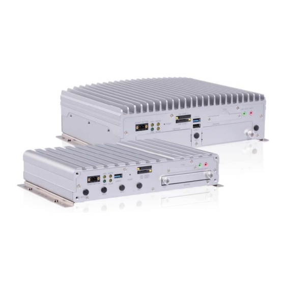
Page 16: Chapter 2 Overview
Introduction Chapter 2 Overview Front View 2.1.1 GV-MNVR1000 System Figure 2-1 No. Name No. Name Event Button (Not Functional) Audio Line Out Port HDD Status LED Audio Microphone In Port WWAN LED 2.5” HDD/SSD Slot USB 3.0 Port Antenna Port x 4 Reset Button WLAN LED SIM Card Slot x 2... -
Page 17: Gv-Mnvr2100 System
2.1.2 GV-MNVR2100 System Figure 2-2 No. Name No. Name Event Button (Not Functional) Audio Line Out Port HDD Status LED Audio Microphone In Port WWAN LED Antenna Port x 3 Reset Button 2.5” HDD/SSD Slot x 2 SIM Card Slot x 2 USB 2.0 Port USB 3.0 Port WLAN LED... -
Page 18: Status Indicator Leds
Introduction 2.1.3 Status Indicator LEDs See the below descriptions for each status LED. HDD LED WWAN LED WLAN LED Power LED Figure 2-3 Indicator LED Color Description HDD LED Orange Glows when HDD/SSD is active. WWAN LED Orange Glows when the WWAN is active. WLAN LED Orange Glows when the WLAN is active. -
Page 19: Rear View
2.2 Rear View 2.2.1 GV-MNVR1000 System Figure 2-4 No. Name No. Name Audio Microphone In Port DC Power Output (Not Functional) Gigabit Ethernet Port x 2 DC 10 ~ 35V Power Input VGA Output GPS Antenna Port USB 2.0 Port x 2 MCU DIO Port (Not Functional) GPIO Terminal Block COM Port x 3... -
Page 20: Gv-Mnvr2100 System
Introduction 2.2.2 GV-MNVR2100 System Figure 2-5 No. Name No. Name Gigabit Ethernet Port x 2 DC 10 ~ 35V Power Input Audio Microphone In Port Antenna Port x 3 USB 3.0 Port MCU DIO Port (Not Functional) DisplayPort COM Port x 3 VGA Output USB 2.0 Port GPIO Terminal Block... -
Page 21: Wireless Antenna
Note: 1. You can freely arrange and switch WiFi and 3G / 4G antennas in ports. 2. GPS module is already built in the GV-Mobile NVR System. WiFi / 3G / 4G modules are optional. Figure 2-6... -
Page 22: Gv-Mnvr2100 System
Note: 1. You can freely arrange and switch WiFi and 3G / 4G antennas in ports. 2. GPS module is already built in the GV-Mobile NVR System. WiFi / 3G / 4G modules are optional. Figure 2-8... -
Page 23: Chapter 3 Getting Started
Chapter 3 Getting Started 3.1 Interface Connection This section describes the equipments required to operate the GV-Mobile NVR System. Here we use the GV-MNVR2100 System for example. Rear Side HDD/SSD x 2 Front Side Figure 3-1... - Page 24 Getting Started 1. There are two options for connecting the power. Connect the GV-Mobile NVR System to the vehicle’s power battery and ACC wire using the supplied 3-pin terminal block. The system will automatically start after you turn on the vehicle ignition. Power is supplied to the system as long as the vehicle ignition is on.
-
Page 25: Turning On And Off The Power
3.2.1 Connecting to the ACC Wire To turn on the GV-Mobile NVR System, connect the vehicle’s ACC and power wires to the unit’s power input using the supplied 3-pin terminal block. The system will automatically start after you power on the vehicle for 5 seconds. - Page 26 Getting Started Using Rocker Switch to Simulate ACC Ignition For quick control of turning on or off the GV-Mobile NVR System, you can install a rocker switch to the 3-pin terminal block with the optional power adapter. For the connection and operation, follow the steps below.
- Page 27 5. To turn off the GV-Mobile NVR System, press the rocker switch again. Note: After the power is on, the GV-Mobile NVR System will run a series of self-tests, and a series of messages may be displayed as the various hardware and software subsystems are activated.
-
Page 28: Installing The Storage Drive
Getting Started 3.3 Installing the Storage Drive The GV-Mobile NVR System uses SATA hard drive / SSD for video data storage. Before recording, be sure to install the storage drive. 3.3.1 GV-MNVR1000 System 1. Loosen the thumb screws on the HDD/SSD slot and pull out the drive drawer. -
Page 29: Gv-Mnvr2100 System
3.3.2 GV-MNVR2100 System 1. Loosen the thumb screws on the HDD/SSD slots and remove the covers. Figure 3-11 2. Press the release latch and pull out the drive drawer using the drawer handle that pops out. Release Latch Figure 3-12 3. - Page 30 Getting Started 4. Secure the storage drive with the drive drawer using the supplied 4 screws. Figure 3-14 5. Insert the drive drawer into the HDD/SSD slot, press the drawer handle back and rotate the release latch until it is vertical to lock the drive drawer. Figure 3-15 6.
-
Page 31: Formatting The Storage Drive
3.4 Formatting the Storage Drive After installing HDD / SSD to your system, you will need to format the storage drive before recording. 1. On the GV-Desktop, click the Programs button, and select Disk Management. Figure 3-16 2. Type the ID and password in the dialog box. The default ID and password are “0000”. Figure 3-17... - Page 32 Getting Started Right-click in the unallocated space of a new drive, and select New Simple Volume. Figure 3-18 4. The New Simple Volume Wizard appears. Click Next to continue. Figure 3-19...
- Page 33 5. The default partition size is the same as the maximum disk space. Make changes if necessary and click Next to continue. Figure 3-20 6. Assign a drive path that is not in use by other devices and click Next to continue. Figure 3-21 Note: The default drive path starts from D:\.
- Page 34 Getting Started Type a name in the Volume label box, ex. HDD1, and click Next to continue. Figure 3-22 8. When the formatting is complete, click Finish to close the wizard. Figure 3-23...
- Page 35 9. When the drive is successfully initialized, partitioned, and formatted, its status description should display “Healthy.” Figure 3-24...
-
Page 36: Adding The Storage Drive To The Recording Path
Getting Started 3.5 Adding the Storage Drive to the Recording Path For GV-Mobile NVR System, you need to add the formatted storage drives to the recording path before recording. On the GV-Desktop, click the Programs button and select Hot Swap HDD Tool. The MediaMan Tools window appears. - Page 37 Note: Storage 1 is the default storage group. 4. Click OK to automatically configure the storage drive to the recording path. 5. In the MediaMan Tools window, if the storage drive is successfully added to store data, its Status field should display “Standby”. Status field Figure 3-27 6.
-
Page 38: Replacing The Storage Drive
Getting Started 3.6 Replacing the Storage Drive You can replace the HDD / SSD without shutting down the GV-Mobile NVR System. 1. Stop the recording and make sure the HDD Status LED (No. 2, Figure 2-1 / 2-2) is off. -
Page 39: Setting Up On-Screen Led Panel
3.7 Setting Up On-Screen LED Panel For GV-Mobile NVR System, a LED panel on the screen provides a quick indication of the activity status of the storage drives. Figure 3-28 LED Color Description - No storage drive is assigned to this LED. - Page 40 Getting Started LED Panel always stays on top: This option makes the LED panel stay on top of other windows when the Media Man Tools window is minimized. Synchronize the LED Panel with the LED Device on GV-Mobile DVR: Not ...
-
Page 41: Configuring The Ip Address
3.8 Configuring the IP Address GV-Mobile NVR System supports remote monitoring, control and configuration over a network connection. The following default IP addresses will automatically be assigned. Connection 1: 192.168.0.200 Connection 2: 192.168.0.201 Default Subnet Mask: 255.255.252.0... - Page 42 Getting Started 2. Type the ID and password. The default ID and password are “0000”. The Control Panel window appears. 3. Under Network and Internet, click View network status and tasks. Figure 3-32 4. Under Connections, select the Local Area Connection you want to configure. Figure 3-33 5.
- Page 43 6. Select Use the following IP address and type the new IP information in the fields. Or select Obtain an IP address automatically to enable dynamic IP address. Figure 3-35 7. Click OK to finish the setting.
-
Page 44: Exiting To Windows
Getting Started 3.9 Exiting to Windows GV-Mobile NVR System is protected by GV-Desktop that is limited to run the selected programs. If you need to exit to Windows desktop, follow these steps. 1. Exit the main screen to display the GV-Desktop screen. -
Page 45: Returning To Gv-Desktop
3.10 Returning to GV-Desktop To return to GV-Desktop, click the Windows Start button, point to All Programs, click GV-NVR, and click Key Lock Utility. Figure 3-38... -
Page 46: Setting Up Twin View Display
Getting Started 3.11 Setting Up Twin View Display You can display live view and play back video in two separated monitors. 1. Follow Steps 1 and 2 in 3.8 Configuring the IP Address to access the Control Panel window. 2. In the Control Panel window, click Adjust Screen Resolution under the Appearance and Personalization section. - Page 47 8. Click the Up button on the toolbar, go to the system folder and locate DMPOS.exe. Figure 3-40 9. Double-click DMPOS.exe. The Set Application Function Position dialog box appears. Figure 3-41 10. In the Screen Setup tab, select TwinView from the Displayer Mode drop-down list. 11.
-
Page 48: Setting Up Digital Matrix
Getting Started 3.12 Setting Up Digital Matrix To display multiple channels through two monitors, Digital Matrix is thus introduced to provide a method. The Digital Matrix includes these features: Live view: You can set different live views and screen divisions for each monitor. ... -
Page 49: Setting Live View
3.12.2 Setting Live View You can set different live views and screen divisions for each monitor. 1. On the main screen, click the Configure button, click Accessories, and select Digital Matrix Setting. This dialog box appears. Figure 3-42 2. Use the Display list to select the monitor to be configured. 3. -
Page 50: Setting Scanned
Getting Started 3.12.3 Setting Scanned Pages You can set up to 16 scanned pages with different screen divisions and channels for each monitor. 1. Use the Display list to select the monitor to be configured. 2. In the upper-left column, expand the Matrix folder tree, and click Page 1. This page appears. -
Page 51: Setting Pop-Up Alert
3.12.4 Setting Pop-up Alert You can be alerted by pop-up live videos when motion is detected or I/O devices are triggered. 1. Use the Display list to select the monitor to be configured. 2. In the upper-left column, click Event Popup. This page appears. Figure 3-44 ... - Page 52 Getting Started 3.12.4.1 Setting Pop-up Positions When you select Random Position of Camera, you can decide the positions for pop-up cameras. Fixed Position of Camera: The cameras pop up in their assigned positions. To assign positions, select Screen Division. Then drag and drop the cameras number to the desired potions on the divisions.
-
Page 53: Setting Live View With Pop-Up Alert
3.12.5 Setting Live View with Pop-up Alert You can set a different live view mode with pop-up alert together for each monitor. When alert events occur, the live video of the associated camera will pop up on the assigned monitor to replace its live view mode. -
Page 54: Updating Gv-Mobile Nvr System
Getting Started 3.13 Updating GV-Mobile NVR System If you like to update your GV-Mobile NVR System, contact your dealer for more information. Before contacting your dealer, you may check software update news at our website: http://www.geovision.com.tw... -
Page 55: Chapter 4 System Restoration
Note: After recovery, you need to re-install all settings and passwords. But the recovery will not delete your recording files saved on the GV-Mobile NVR System since it only reformats the partition C and all of your files are still stored on other partitions. - Page 56 System Restoration 4. When the below screen appears, press the Recovery button. Figure 4-2 5. When the restoring process is completed, the screen will automatically show the GV-Desktop, and the system will restore the default values.
-
Page 57: Chapter 5 Health Analysis
Chapter 5 Health Analysis GeoVision offers health analysis to GV-Mobile NVR System. The service is intended to give diagnosis for early and immediate detection of problems. It is recommended to have the health analysis during the first week after you install the GV-Mobile NVR, and then have the checkup every three months. - Page 58 Health Analysis 2. Select Backup MultiCam Settings or Restore Defaults, and select Backup Current System. This dialog box appears. Figure 5-2 3. Press the Next Step button to back up all your system settings. The Save As dialog box appears. 4.
-
Page 59: System Log
5.2 System Log Please provide the sys*.mdb files of system log. The files by default are saved at C:\GV folder\database. If you have modified the default location, you can check the path by the following steps: 1. Click the Configure button on the Main System, select System Configure, and then select System Log Setting. -
Page 60: Information Of Your Computer System
Health Analysis 5.3 Information of Your Computer System To get the information of your computer system, please follow the steps below to install the free software PC WIZARD. By using the software, the following computer information can be easily collected and saved for analysis: Processor: includes Type, Frequency, Data Cache L1, Trace Cache L1, Cache L2, ... - Page 61 4. In the Save As dialog box, select Format HTML and click OK. Figure 5-5 5. Select the Save location, type the file name, and then click Save to save the Processor information as HTML file. 6. Repeat Steps 3-5 to save the Drives information as HTML file.
-
Page 62: Health Analysis Form
Health Analysis 5.4 Health Analysis Form Please send the related data for analysis along with this Health Analysis Form to dvrsystem@geovision.com.tw. Health Analysis of GV-Mobile NVR System Contact Person: Title: Company Name: Telephone: (O) Fax: E-Mail: Model: Bar Code: 5.5 Check List... -
Page 63: Chapter 6 Troubleshooting
Chapter 6 Troubleshooting GV-Mobile NVR storage drive becomes corrupted. If you are experiencing file system corruption problems, such as lost clusters, cross-linked files or invalid files or directories, try these steps: 1. Use the HD Tune utility to scan the storage drive for errors. Follow these steps: A. - Page 64 Troubleshooting 2. If the HD Tune utility does not find any defects, use the Windows built-in utility to attempt to fix the errors. Follow these steps: A. On the GV-Desktop, click the Programs button, and select Disk Management. See Figure 3-16. B.
- Page 65 Click the Search button of the IP Device Utility again to detect the GV-IP cameras. Black images are displayed. Check the IP cameras and make sure they are functioning well. Check the GV-Mobile NVR System’s connection over network. How can I find more help? Visit our website at http://www.geovision.com.tw/english/4_1.asp...
-
Page 66: Specifications
Specifications Specifications Hardware Model GV-MNVR1000 GV-MNVR2100 System Intel Atom Processor Intel Core i3 Processor 2 GB Single Channel 4 GB Dual Channels 64-bit Windows Embedded Standard 7 SP1 32 GB (CFast Card) Internal Storage No. of Drive Bay 1 (2.5” HDD / SSD) 2 (2.5”... - Page 67 Video Codec MJPEG / MPEG4 / H.264 32 kHz / 16 bit Audio Codec Dual Streams from Dual Streams from Video Stream GeoVision IP Cameras 3rd-party IP Cameras 1 MP 20 channels 20 channels 2 MP 17 channels 17 channels...
- Page 68 Specifications Note: It is required to enable the dual-stream function on GeoVision and third-party IP cameras to have the maximum number of channels supported. For single streaming third-party IP cameras, please see "Maximum Channels and Frame Rate Supported" later in this manual.
- Page 69 Language Arabic / Bulgarian / Czech / Danish / Dutch / English / Finnish / French / German / Greek / Hebrew / Hungarian / Italian / Japanese / Lithuanian / Norwegian / Polish / Type Portuguese / Romanian / Russian / Serbian / Simplified Chinese / Slovakian / Slovenian / Spanish / Swedish / Thai / Traditional Chinese / Turkish Software License...
-
Page 70: Appendix
Appendix Appendix Supported IP Devices This list provides the supported IP device brands. For detailed information on the supported IP devices, refer to Supported IP Camera List on GeoVision’s website: http://www.geovision.com.tw/english/4_21.asp GeoVision ACTi Arecont Vision AXIS Bosch Canon D-Link Etrovision... -
Page 71: Warranty Policy
Warranties do not apply to any non-GeoVision products including counterfeited products. GeoVision is not liable for any damage to or loss of any profit, programs, data, or other information stored on any media, or any non-GeoVision products or part not covered by these warranties. - Page 72 Regardless whether any remedy set forth herein fails of its essential purpose or otherwise, in no event will GeoVision or its suppliers be liable for any lost revenue, profit or lost or damaged data, business interruption, loss of capital, or for special, indirect, consequential, incidental, or...
- Page 73 GeoVision Products or otherwise and even if GeoVision has been advised of the possibility of such damages. In no event shall GeoVision's liability to...
-
Page 74: Warranty Requirements
To validate your purchase, you shall complete the online Product Registration within 30 days from the date of purchase at http://www.geovision.com.tw/english/4_6.asp. Or click GeoVision Online Registration in My Favorite for a direct link. If you fail to complete the Product Registration, the warranty period will start from the date of shipment. - Page 75 2. Securely pack the product in its original carton using the original packing material, or in equivalent packaging. 3. The product shall be returned to GeoVision, Taiwan at your expense for shipping and insurance costs. BEFORE YOU DELIVER YOUR GV-MOBILE NVR SYSTEM FOR WARRANTY SERVICE, IT IS YOUR RESPONSIBILITY TO BACK UP YOUR DATA.
-
Page 76: Warranty Form
Warranty Form Warranty Form Thank you for purchasing the GV-Mobile NVR System. To help us validate your purchase and better serve you in the future, please go to http://www.geovision.com.tw/english/4_6.asp click GeoVision Online Registration in My Favorite for a direct link to register online within 30 days from the date of purchase. - Page 77 Bar Code: Shipment Date: GeoVision, Inc. 9F, No. 246, Sec. 1, Neihu Rd., Neihu District, Taipei, Taiwan Tel: +886-2-8797-8377 Fax: +886-2-8797-8335 Email: sales@geovision.com.tw dvrsystem@geovision.com.tw http://www.geovision.com.tw...
Need help?
Do you have a question about the GV-Mobile NVR System and is the answer not in the manual?
Questions and answers