Table of Contents
Advertisement
Quick Links
Quick Start Guide
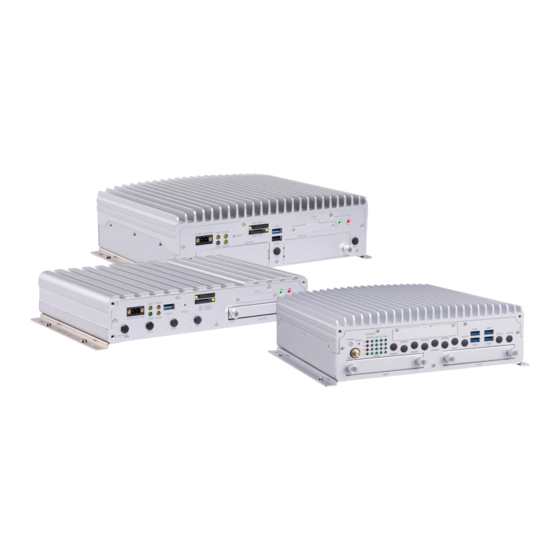
GV-Mobile System
The Vision of Security
Thank you for purchasing GV-Mobile System. This guide is designed to assist the new user in getting immediate results
from the GV-Mobile System. For advanced information on how to use the GV-Mobile System, please refer to
GV-Mobile System User's Manual (C:\UserManual).
2020/04
English
MB2700-QG-A
Advertisement
Table of Contents

Related Manuals for GeoVision GV-MNVR1000


Summary of Contents for GeoVision GV-MNVR1000
- Page 1 Quick Start Guide GV-Mobile System The Vision of Security Thank you for purchasing GV-Mobile System. This guide is designed to assist the new user in getting immediate results from the GV-Mobile System. For advanced information on how to use the GV-Mobile System, please refer to GV-Mobile System User’s Manual (C:\UserManual).
- Page 2 GeoVision. Every effort has been made to ensure that the information in this manual is accurate. GeoVision, Inc. makes no expressed or implied warranty of any kind and assumes no responsibility for errors or omissions. No liability is assumed for incidental or consequential damages arising from the use of the information or products contained herein.
-
Page 3: Table Of Contents
1.5.3 GV-MNVR2110 – Front View ....................6 1.5.4 GV-MNVR2110 – Rear View ....................7 1.5.5 Status Indicator LEDs of GV-MNVR1000 / GV-MNVR2110 ............ 7 1.5.6 GV-Mobile System 2700 – Front View ..................8 1.5.7 GV-Mobile System 2700 – Rear View ..................9 1.5.8 Status Indicator LEDs of GV-Mobile System 2700 .............. - Page 4 3.3 Playing Back Video ........................35 3.4 Playback Controls ........................36 3.5 Backing Up Video Files ......................36 3.6 Playing Backup Files......................... 38 4B4. Accessing GV-Mobile System (VMS Model) ................39 4.1 Main Screen ..........................39 4.1.1 Adding Storage Drive to Recording Path ................40 4.1.2 Adding IP Cameras to GV-VMS .....................
-
Page 5: Introduction
1.1 Packing List 1. GV-Mobile System 2. 3-pin Terminal Block (for ACC Connection and DC In) 3. HDD screw x 4 (for GV-MNVR1000) 4. HDD screw x 8 (for GV-MNVR2110 / GV-Mobile System 2700) 5. GPS Antenna 6. GV-NVR Dongle for third-party IP Camera Connection (Optional) 7. -
Page 6: Software License
1.3 Software License GV-MNVR1000 / GV-MNVR2110 / GV-Mobile System 2700 (NVR Model) Free License 24 / 32 / 32 channels from GV-IP Devices Maximum Paid License 24 / 32 / 32 channels from third-party IP devices Increment for Each 1 to 24 / 32 / 32 third-party IP cameras, in increments of 2 ch... -
Page 7: Options
GV-TouchDisplay133 GV-Mobile System. With the touch panel, you can monitor live images and operate GV-NVR by simply touching the screen. GV-MNVR1000 / GV-MNVR2110: Australia / Europe / U.K. / U.S.A. Power Adapter GV-Mobile System 2700: Argentina / Australia / Brazil / Europe / U.K. -
Page 8: Overview
1.5 Overview 1.5.1 GV-MNVR1000 – Front View No. Name No. Name Event Button (Not Functional) Audio Line Out Port HDD Status LED Audio Microphone In Port 2.5” HDD/SSD Slot WWAN LED USB 3.0 Port Antenna Port x 4 Reset Button... -
Page 9: Gv-Mnvr1000 - Rear View
1.5.2 GV-MNVR1000 – Rear View No. Name No. Name Audio Microphone In Port DC Power Output (Not Functional) Gigabit Ethernet Port x 2 DC 10 ~ 35V Power Input VGA Output GPS Antenna Port USB 2.0 Port x 2 MCU DIO Port (Not Functional) -
Page 10: Gv-Mnvr2110 - Front View
1.5.3 GV-MNVR2110 – Front View No. Name No. Name Event Button (Not Functional) Audio Line Out Port HDD Status LED Audio Microphone In Port WWAN LED Antenna Port x 3 Reset Button 2.5” HDD/SSD Slot x 2 SIM Card Slot x 2 USB 2.0 Port USB 3.0 Port WLAN LED... -
Page 11: Gv-Mnvr2110 - Rear View
USB 2.0 Port GPIO Terminal Block GPS Antenna Port (Not Functional) DC Power Output (Not Functional) Audio Line Out Port Fuse (15A) 1.5.5 Status Indicator LEDs of GV-MNVR1000 / GV-MNVR2110 HDD LED WWAN LED WLAN LED Power LED Indicator LED Color... -
Page 12: Gv-Mobile System 2700 - Front View
1.5.6 GV-Mobile System 2700 – Front View No. Name No. Name Power Button USB 3.1 Port x 4 Reset Button Antenna Port x 10 2.5” HDD/SSD Slot x 2 LED Indicators 6 SIM Slots with Cover GPS Antenna Port... -
Page 13: Gv-Mobile System 2700 - Rear View
1.5.7 GV-Mobile System 2700 – Rear View No. Name Name Audio Microphone In Port Audio Microphone In Port DC 9 ~ 36V Power Input Audio Line Out Port HDMI Port COM Port x 3 LAN Port CAN/DIO Port (Not Functional) PoE Port x 4 VGA Port DC Power Output... -
Page 14: Status Indicator Leds Of Gv-Mobile System 2700
1.5.8 Status Indicator LEDs of GV-Mobile System 2700 Storage LED LAN LED WWAN LED PoE LED LAN link and active LED WLAN LED Programmable LED Indicator LED Color Description WWAN LED x 4 Green Glows when the WWAN is active. Storage LED x 1 Green Glows when HDD/SSD is active. -
Page 15: Wireless Antenna
1. You can freely arrange and switch WiFi and 4G antennas in ports. 2. GPS module is already built in the GV-Mobile System. WiFi / 4G modules are optional. 3. For GV-MNVR1000, see 2.2 GV-MNVR1000 – Rear View in the GV-Mobile System User’ Manual. -
Page 16: 1B2. Getting Started
2. Getting Started 2.1 Interface Connection This section describes the equipment required to operate the GV-Mobile System. Here we use the GV-MNVR2110 System for example. Rear Side HDD/SSD x 2 Front Side 1. There are two options for connecting the power. Connect the GV-Mobile System to the vehicle’s power battery and ACC wire using the supplied 3-pin terminal block. - Page 17 Optionally purchase a power adapter from GeoVision. See 2.2 Turning on and off the Power. 2. Use the VGA cable or the DisplayPort cable to connect the unit to the monitor. Note: The GV-Mobile System supports dual-monitor display. You can connect two monitors by using the VGA connector and DisplayPort.
-
Page 18: Turning On And Off The Power
After you power off the vehicle for 3 seconds, the system will turn off automatically. 2.2.2 Using the Power Adapter To turn on and off the GV-Mobile System using an optional power adapter from GeoVision, follow the steps below. 1. Plug the 3-pin terminal block connected with power adapter to the panel’s power pins. The GV-Mobile System will be powered on about 5 seconds later. - Page 19 Using Rocker Switch to Simulate ACC Ignition For quick control of turning on or off the GV-Mobile System, you can install a rocker switch to the 3-pin terminal block with the optional power adapter. For the connection and operation, follow the steps below. 1.
- Page 20 Note: After the power is on, the GV-Mobile System will run a series of self-tests, and a series of messages may be displayed as various hardware and software subsystems are activated. After the process is finished, GeoVision software will be loaded automatically and bring you to the main screen.
-
Page 21: Installing The Storage Drive
The GV-Mobile System uses SATA hard drive / SSD for video data storage. Before recording, be sure to install the storage drive. 2.3.1 GV-MNVR1000 System 1. Loosen the thumb screws on the HDD/SSD slot and pull out the drive drawer. -
Page 22: Gv-Mnvr2110 System
2.3.2 GV-MNVR2110 System 1. Loosen the thumb screws on the HDD/SSD slots and remove the covers. 2. Press the release latch and pull out the drive drawer using the drawer handle that pops out. Release Latch 3. Insert the storage drive into the drive drawer with the SATA data and power connector facing towards the end. - Page 23 2.3.3 GV-Mobile System 2700 1. Loosen the thumb screws on the HDD/SSD slot and pull out the drive drawer. 2. Put the black anti-vibration dampers into the holes on the drive drawer. 3. Insert the storage drive into the drive drawer with the SATA data and power connector facing towards the end.
-
Page 24: Formatting The Storage Drive
After installing HDD / SSD to your system, you will need to format the storage drive before recording. For GV-MNVR1000 / GV-MNVR2110: 1. Click the Programs button on the GV-Desktop, and select Disk Management. 2. Type the ID and password in the dialog box. The default ID and password are “0000”. - Page 25 3. Skip to Step 7. For GV-Mobile System 2700: 4. Right-click the Computer icon on your desktop, select Manage, and select Disk Management when the Computer Management window appears. 5. On the main page of Disk Management, the Initialize Disk dialog box appears for the new drive.
- Page 26 8. The New Simple Volume Wizard appears. Click Next to continue. 9. The default partition size is the same as the maximum disk space. Make changes if necessary. Click Next to continue. 10. Assign a drive path that is not in use by other devices, and click Next to continue. Note: The default drive path starts from D:\.
- Page 27 11. Type a name in the Volume label box, ex. HDD1, and click Next to continue. 12. When the formatting is complete, click Finish to close the wizard. When the drive is successfully initialized, partitioned, and formatted, its status description should display “Healthy”.
-
Page 28: Configure The Ip Address
2.5 Configure the IP Address GV-Mobile System supports remote monitoring, control and configuration over a network connection. For GV-MNVR1000 / GV-MNVR2110, the following default IP addresses will automatically be assigned. • Connection 1: 192.168.0.200 • Connection 2: 192.168.0.201 • Default Subnet Mask: 255.255.252.0 Note: GV-Mobile System 2700 does not have a default IP address. - Page 29 3. Under Network and Internet, click View network status and tasks. 4. Under Connections, select the Local Area Connection you want to configure. 5. Select Internet Protocol Version 4 (TCP/IPv4), and select Properties.
- Page 30 6. Select Use the following IP address and type the new IP information in the fields. Or select Obtain an IP address automatically to enable dynamic IP address. 7. Click OK to finish the setting.
-
Page 31: Exiting To Windows
2.6 Exiting to Windows The unit is protected by GV-Desktop that is limited to run the selected programs. For GV-MNVR1000 / GV-MNVR2110, follow the steps below to exit to Windows desktop. Note: GV-Desktop is not supported by GV-Mobile System 2700. -
Page 32: 4B3. Accessing Gv-Mobile System (Nvr Model)
3. Accessing GV-Mobile System (NVR Model) 3.1 Main Screen 1. Logout / Exit / Minimize 8. Start/stop screen rotation 2. Select screen divisions 9. Access remote applications 3. Select a camera for full screen mode 10. Camera Name 4. Start/stop recording 11. -
Page 33: Adding A Storage Drive To The Recording Path
3.1.1 Adding a Storage Drive to the Recording Path Before recording, you need to add the formatted storage drive to the recording path. 1. Click the Programs button on the GV-Desktop and select Hot Swap HDD Tool. The MediaMan Tools window appears. 2. - Page 34 B. Select Add to recording path, and select the storage group from the drop-down list. Note: Storage 1 is the default storage group. 6. Click OK to automatically configure the hard drive to the recording path. 7. In the MediaMan Tools window, if the hard drive is successfully added to store data, its Status field should display “Standby”.
-
Page 35: Adding Ip Video Devices
3.1.2 Adding IP Video Devices The procedures for adding an IP camera, Video Server and Compact DVR may vary. The following instructions are the setup procedure for adding an IP camera in the system. 1. On the main screen, click the Configure button, select System Configure and click IP Camera Install. -
Page 36: Renaming The Camera
5. The options in the dialog box may vary depending on camera brands. • Dual Streams: Click the button to apply the default codec and resolution of GV-IP camera. • Query: Use the current codec and resolution setting on GV-IP camera. •... -
Page 37: Choosing Recording Mode
3.1.4 Choosing Recording Mode You can set each camera's recording mode individually for Motion Detection, Round-the-Clock or Day-Night. 1. Click on the main screen, click System Configure and select Camera Configure. 2. From the Camera Name drop-down list, select one camera. 3. -
Page 38: Setting Up A Recording Schedule
3.2 Setting up a Recording Schedule You can program recording to turn on and off at a specific time each day. 1. Click on the main screen, and select Schedule Edit. 2. Select or enter the Start and End time of the schedule. 3. -
Page 39: Playing Back Video
3.3 Playing Back Video You can play back video recorded during a particular date and time. 1. Click on the main screen, and select Video/Audio Log. 2. Select the camera you wish to view. 3. Select a date folder from the date tree. 4. -
Page 40: Playback Controls
3.4 Playback Controls Description Description Rewind to Beginning Speed up/down Frame-by-Frame Reverse Zoom in/out Rewind A to B Playback Stop Frame-by-Frame / Real Time Playback Play Playback Scroll Frame-by-Frame Forward Audio on/off Forward to End Using the Zoom ◼ Zoom in: Click the Zoom-in button, and then click on the area you want to magnify. Each click will increase the zoom level. - Page 41 8. Select the types of events for backup, e.g. video, audio or both together. 9. Click OK to add the time frame. You can repeat steps 5-8 to create up to 10 time frames. 10. Click OK to start burning.
-
Page 42: Playing Backup Files
3.6 Playing Backup Files Open the backup folder, run EZViewLog500.exe, and then follow the instructions in the Play Back Video section. -
Page 43: 4B4. Accessing Gv-Mobile System (Vms Model)
Brings up these options when Home is selected: ⚫ Monitor: Start / Stop monitoring, I/O monitoring and schedule monitoring ⚫ Network: Enable Webcam Server and connection to other GeoVision software. ⚫ Tools: Show / hide volume indicator and set up Object Index. ⚫... -
Page 44: Adding Storage Drive To Recording Path
4.1.1 Adding Storage Drive to Recording Path 1. On GV-VMS, click Home , select Toolbar , select Configure , select System Configure, and click Record Setting. This dialog box appears. 2. Click the Arrow button next to Storage. This dialog box appears. 3. -
Page 45: Adding Ip Cameras To Gv-Vms
A. To add a new folder in the first storage group, click the Add button on the right pane and select a folder. Only 1 folder can be assigned as storage folder for each partition (e.g. only 1 folder in D drive). B. - Page 46 3. The cameras added are now listed in the IP Device List. Status icons available: Connected The camera is connected. Connecting GV-VMS is trying to connect to the camera. Connection Failed Unable to connect to the camera. Move the cursor on the red icon to see the error message.
-
Page 47: Configuring Camera Settings
4.2 Configuring Camera Settings After the cameras are added, you can configure their settings, such as video, audio and other general settings. Click Setup of an active camera in the IP Device List (Home > Toolbar > Configure > Camera Install). In the Video Setting, you can change the camera name, the display ration and resolution of the videos and adjust video attributes. -
Page 48: Playing Back Recorded Videos
4.3 Playing Back Recorded Videos To access recorded videos, click the ViewLog icon in the top-right corner. To open the Content List, click Toolbar and select Content List Click Layout in the Content List, click Add , and select Add Layout to create a new layout or select Import from Live to import existing layouts from live view. -
Page 49: Backing Up Recorded Videos
Click on the timeline to select a time with video recordings. You can scroll the mouse to zoom in and out on the timeline. Use the playback control buttons to play back recordings. Place the cursor on the buttons to see the name of the function. 4.4 Backing Up Recorded Videos In ViewLog, click Toolbar , select Tools... -
Page 50: 8B5. System Restoration
5. System Restoration You can restore the operating system and system software back-up files using Windows Tool. Refer to the instructions here.
Need help?
Do you have a question about the GV-MNVR1000 and is the answer not in the manual?
Questions and answers