Table of Contents
Advertisement
Quick Links
Advertisement
Table of Contents

Related Manuals for Impulse IT8016


Summary of Contents for Impulse IT8016
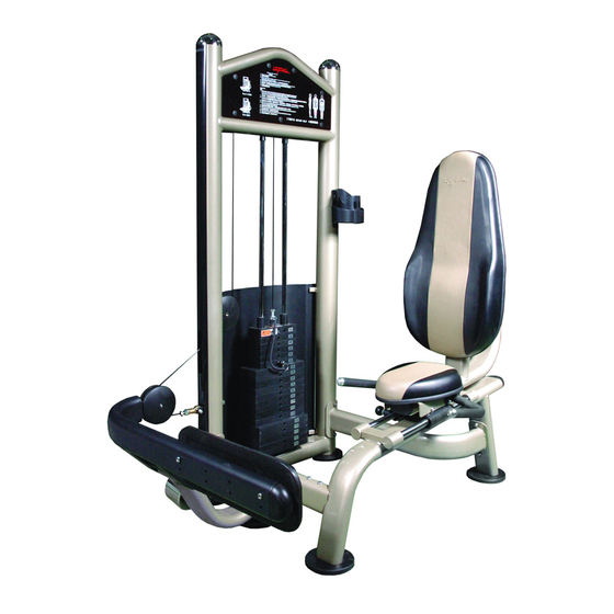
- Page 1 T8016 Rotary Calf Assembly Instructions...
-
Page 2: Table Of Contents
Table of contents Important Safety Instructions--------------------------------- 1 Exploded View Diagram------------------------------------------ 2 Hardware List-------------------------------------------------- ------ Parts List----------------------------------------------------- ---------- Assembly instructions------------------------------------------... -
Page 3: Important Safety Instructions
Important Safety Instructions Before beginning any fitness program, you should obtain a complete physical examination from your physician. When using exercise equip- ment, basic precautions should always be taken, including the following: * Read all instructions before using the Rotary Calf These instructions are written to ensure your safety and to protect the unit. -
Page 4: Exploded View Diagram
T8016 Rotary Calf Exploded View Diagram... -
Page 5: Hardware List
Hardware List 1 10 14 0 Millimeters Inches... -
Page 6: Parts List
Parts List Item No. Description QTY Item No. Description Foot Plate Main Upright Front Cross Frame Allen Bolt M10×75 Swive lFrame End Cap 50×100 Seat Support Flat End Cap 50×100 Rubber Cap Slide Frame Counter Poise Block Rear Cross Frame Left Bearing Holdle Adj. -
Page 7: Assembly Instructions
Assembly instructions Assembly of the Rotary Calf takes professional installers about 2 hours. If this is the first time you have assembled this type of equipment, plan to spend more time. It is strongly recom men- to assemble the equipment by professional installers. You may find it quicker, safer, easier to assemble this equipment with the help of a friend, as some of components may be large, heavy or awkward to handle alone. -
Page 8: Seat Support 1
Step1 Install the Adj. Foot Plates Align the Adj. Foot Plates(#47) to the Main Upright(#1), the Seat Support(#4) and the Front Cross Support(#2) then secure them by hands. -
Page 9: Rear Cross Frame 1
Step2 Assemble The Frame 1)Attach the Front Cross Frame(#2) and the Low Rear Cross Frame(#6)to the Main Upright(#1) using: four Allen Bolts(#52) M10×115 four Nylon Locknuts(#67) M10 eight Washers(#64) Φ 11× 20×2 Φ 2)Attach the seat support(#4) to the Low Cross Frame (#2) and the Rear Cross Frame(#6) and secure it using: two Allen Bolts(#52) M10×120 two Allen Bolts(#53) M10×70... - Page 10 Step3 Assemble The Foot Plate 1)Attach the Foot Plate (#41) to the Swivel Frame(#3) using: eight Allen Bolts(#57) M8×60 eight Washers(#65) 9× 16×1.6 Φ Φ 2)Attach the Counter Poise Block(#46) to the swivel frame(#3) using: two Shoulder Bolts(#59) M8×30 two Spring Washers(#61) Φ...
- Page 11 Step4 Assemble The Swivel Frame 1)Attach the Swivel Frame(#3)to the Front Cross Frame (#2) using: one Shaft(#12) two Allen Bolts(#62) M8×15 2)Attach the Counter Poise Block(#46) to the Swivel Frame(#3) using: two Allen Bolts(#59) M8×25 two Spring Washers(#61) Φ...
- Page 12 Step5 Assemble The Slide Frame 1)Attach the Seat Pad(#14) to the Slide Frame(#5) using: two Allen Bolts(#42) M10×75 two Washers(#64) Φ 11× 20×2 Φ 2)Attach the Right Bearing Holder(#8) and the Right Ha- ndle(#10) to the Slide Frame(#5)using: three Allen Bolts(#55) M10×25 three Spring Washers(#68) Φ...
-
Page 13: Slide Guide 2
Step6 Assemble The Slide Guides Align the Slide Frame(#5) to the Seat Support(#4),insert both Slide Guides(#11) through the Seat Support(#4) and the two Bearing Holders(#7,#8) located under the Slide Frame(#5) and secure them using: two Allen Bolts(#62) M8×15... - Page 14 Step7 Assemble The Guide Rods 1)Insert both the Guide Rods(#19) into the Main Upright (#1). 2)Slide the Weight Rubber Bumper(#30) down onto each Guide Rod(#19). 3)Carefully begin sliding the Weight Plate one by one in sequence:#34,#33,#32,#31. 4)Align both top ends of the Guide Rods(#19) to the Main Upright(#1)and secure them using: two Spring Washer(#68) Φ...
- Page 15 Step8 Route The Cable 1)Put the clip tied on the weight pin leash onto the Top Plate(#31) as shown, next connect the Cable(#18) to the Top Plate(#31). 2)Route the Cable(#18) up and over the two Pulleies A (#25).then secure them to the Main Upright(#1) using: two Allen Bolts(#54) M10×45 four Washers(#64) Φ...
- Page 16 Step9 Assemble The Decal Plates 1)Attach the two Decal Plates(#21,#22) to the Main Up- right(#1) using: fourteen Butttons(#36) 2)Attach the Weight Shroud (#23)to the Main Upright (#1) using: four Bolt Covers(#38) four Plastic Washers(#37) four Chamfer Bolts(#60) The Front Decal Plate(#21) with the exercise instr- uctions printed on it should be attached in the front Note of the Main Upright(#1).
-
Page 17: Back Pad(
Step10 Assemble Pads Attach the Back Pad(#15) to the Slide Frame(#5) using: three Washers(#64) Φ 11× 20×2 Φ two Allen Bolts(#56) M10×30 one Allen Bolt(#53) M10×70 Attach the Plastic Cap(#79) to the Main Upright(#1) using: two Screws(#80) M6×15 For a safe exercise,you need make the unit steady by adjusting the Adj.foot plates.
Need help?
Do you have a question about the IT8016 and is the answer not in the manual?
Questions and answers