Table of Contents
Advertisement
Quick Links
Advertisement
Table of Contents

Related Manuals for Printronix T600


Summary of Contents for Printronix T600
- Page 1 T600 Printer Administrator’s Manual Thermal Printer...
- Page 2 Software without notice at any time. documentation. The Software Product is licensed (not sold) to you, and Printronix Auto ID Technology, Inc. either owns IN NO EVENT WILL PRINTRONIX AUTO ID TECHNOLOGY, INC. BE LIABLE FOR LOST...
- Page 3 Printronix Auto ID Technology, Inc. All non-Printronix registered and/or unregistered trademarks used throughout this manual are the sole property of their respective owners. COPYRIGHT © 2016 PRINTRONIX AUTO ID TECHNOLOGY, INC. All rights reserved.
- Page 4 -Connect the equipment into an outlet on a circuit different from that to which the receiver is connected. -Consult the dealer or an experienced radio/ TV technician for help. This device complies with Part 15 of the FCC Rules. Operation is subject to the following two conditions: (1) This device may cause harmful interference, and (2) this device must accept any interference received, including interference that may cause undesired operation.
- Page 5 Note: * Continuous printing will cause the printer motor to overheat. The printer will stop printing automatically for about 10~15 minutes while the motor is cooling down. Do not turn the power off when the printer pauses or the data transferred to the printer buffer will be lost. * The maximum printing ratio per dot line is 15% for this printer.
-
Page 6: Table Of Contents
Contents 1. Introduction ............................1 1.1 Product Introduction ........................1 1.2 Product Features .......................... 2 1.2.1 Printer Standard Features ..................... 2 1.2.2 Printer Optional Features ...................... 3 1.3 General Specifications ......................... 3 1.4 Print Specifications ........................4 1.5 Ribbon Specifications ........................4 1.6 Media Specifications ........................ - Page 7 5.1 Ribbon and Gap/Black Mark Sensor Calibration................ 29 5.2 Gap/Black Mark Calibration, Self-test and Dump Mode ............30 5.3 Printer Initialization ........................34 5.4 Set Black Mark Sensor as Media Sensor and Calibrate the Black Mark Sensor ....... 35 5.5 Set Gap Sensor as Media Sensor and Calibrate the Gap Sensor ..........36 5.6 Skip AUTO.BAS .........................
-
Page 9: Introduction
1. Introduction 1.1 Product Introduction Thank you very much for purchasing this bar code printer. This series of thermal transfer desktop barcode printer, label printer with its new, smaller footprint, offers the high performance that customers have come to expect. Durable, reliable and fast, this series generates 4-inch-wide labels, tags or receipts at up to 6 ips, offering a price-performance combination that is unmatched by other desktop thermal barcode printers on the market. -
Page 10: Product Features
1.2 Product Features 1.2.1 Printer Standard Features The printer offers the following standard features. Product standard feature Thermal transfer/ or direct thermal 6 operating buttons and 1 LED with 3 colors 2.3” color TFT display, 320 x 240 pixel (UI of operating menu) 32-bit RISC high performance processor (Atmel 9G25/ 400 MHz) Center alignment holder with spiral spring Gap transmissive sensor (Fixed, center of offset 4 from center) -
Page 11: Printer Optional Features
Supported code page: Codepage 1251 (Cyrillic) Codepage 1252 (Latin-1) Codepage 437 (English - US) Codepage 1253 (Greek) Codepage 737 (Greek) Codepage 1254 (Turkish) Codepage 850 (Latin-1) Codepage 1255 (Hebrew) Codepage 852 (Latin-2) Codepage 1256 (Arabic) ... -
Page 12: Print Specifications
• Input: AC 100-240V/ 2.5A, 50-60 Hz • Output: DC 24V/ 3.75A, 90W Operation: 5 ~ 40˚C (41 ~ 104˚F), 25~85% non-condensing Environmental Storage: -40 ~ 60 ˚C (-40 ~ 140˚F), 10~90% non-condensing condition Environmental Comply with RoHS, WEEE, REACH concern 1.4 Print Specifications Print... -
Page 13: Media Specifications
1.6 Media Specifications Media Specifications Media roll capacity Max. 5” OD Media core diameter 1” & 1.5 ID core Media type Continuous, die-cut, black mark, external fan-fold, notch Media wound type Outside wound Media width 20 mm ~ 112 mm Media thickness 0.06 mm ~ 0.19 mm Label length... -
Page 14: Operations Overview
2. Operations Overview 2.1 Unpacking and Inspection This printer has been specially packaged to withstand damage during shipping. Please carefully inspect the packaging and printer upon receiving the bar code printer. Please retain the packaging materials in case you need to reship the printer. Unpacking the printer, the following items are included in the carton. -
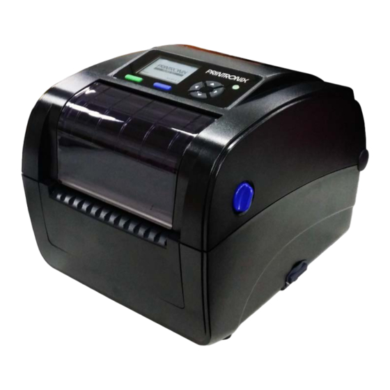
Page 15: Printer Overview
2.2 Printer Overview 2.2.1 Front View LCD display Menu button Feed button LED indicator Navigation button Ribbon access cover Top cover open lever *SD card socket Paper exit chute * Recommended SD card specification SD card spec SD card capacity Approved SD card manufacturer V2.0 SDHC CLASS 4 2 GB Transcend V2.0 SDHC CLASS 4 8 GB... -
Page 16: Interior View
2.2.2 Interior view Ribbon rewind hub Ribbon rewind gear Gap sensor (receiver) Media holder Media holder locking switch Gap sensor (transmitter) Print head Ribbon supply hub Top cover support Media guide adjustment button Media guides Black mark sensor Platen roller P180043-001_A... -
Page 17: Rear View
2.2.3 Rear View Ethernet interface USB interface USB host RS-232C interface Power jack socket Power switch External label entrance chute The interface picture here is for reference only. Please refer to the product specification for the interfaces availability. - 9 - P180043-001_A... -
Page 18: Operator Control
2.3 Operator Control 2.3.1 LED Indication This printer has one three-color LED indicator. LED Color Description Green/ Solid This illuminates that the power is on and the device is ready to use. This illuminates that the system is downloading data from PC to memory Green/ Flash or the printer is paused. -
Page 19: Setup
3. Setup 3.1 Setting up the printer 1. Place the printer on a flat, secure surface. 2. Make sure the power switch is off. 3. Connect the printer to the computer with the provided USB cable. 4. Plug the power cord into the AC power cord socket at the rear of the printer, and then plug the power cord into a properly grounded power outlet. -
Page 20: Open/Close The Top Cover
3.2 Open/Close the Top Cover 1. Open the printer’s top cover by pulling the top cover open levers located on each side of the printer and lifting the top cover to the maximum open angle. 2. A top cover support at the rear of the printer will engage with lower inner cover to hold the printer top cover open. -
Page 21: Loading The Ribbon
3.3 Loading the Ribbon 1. Open the printer’s top cover by pulling the top cover open levers located on each side of the printer and lifting the top cover to the maximum open angle. 2. Open the ribbon access cover and the media cover. - Page 22 4. Insert the paper core right side onto the rewind hub. Align the notches on the left side and mount onto the spokes. 5. Stick the ribbon onto the ribbon rewind paper core. 6. Turn the ribbon rewind gear until the ribbon plastic leader is thoroughly wound and the black section of the ribbon covers the print head.
- Page 23 7. Close the ribbon access cover and the top cover. Loading path for ribbon - 15 - P180043-001_A...
-
Page 24: Loading The Media
3.4 Loading the Media 3.4.1 Loading the Media 1. Open the printer top cover by pulling the tabs located on each side towards the front of the printer then lift the top cover to the maximum open angle. 2. Separate and hold open the media holders. - Page 25 4. Press down the media holder lock switch to hold the label roll firmly. 5. Place the paper, printing side face up, through the media sensor and place the label leading edge onto the platen roller. Move the media guides to fit the label width by turning the guide adjuster knob.
- Page 26 7. Use “Configuration Utility” or LCD menu function to set the media sensor type and calibrate the selected sensor. For Configuration Utility: Start the “Configuration Utility” Select the “T6X0” in the list Click the “Printer Function” button Click the “Calibrate” button Select media sensor type and Click the “Calibrate” button Printer function button: Note: ...
-
Page 27: External Label Roll Mount Installation (Option)
3.4.2 External Label Roll Mount Installation (Option) 1. Attach an external paper roll mount on the bottom of the printer. 2. Insert a 3” label spindle into a paper roll. And install it on the external paper roll mount. 3. Open the printer’s top cover and separate the media holders to fit the media width. - Page 28 4. Feeds the media through the rear external label entrance chute. And place the paper, printing side face up, through the media sensor and place the label leading edge onto the platen roller. Move the media guides to fit the label width by turning the guide adjuster knob.
-
Page 29: Loading Media In Peel-Off Mode (Option)
3.4.3 Loading Media in Peel-off Mode (Option) 1. Please refer to section 3.3.1 to load the media. 2. Use “Configuration Utility” or LCD menu function to set the media sensor type and calibrate the selected sensor. Note: Please calibrate the gap/black mark sensor before loading media in peel-off mode to avoid paper jam. - Page 30 6. Disengage the top cover support to close the top cover. Printer is ready for peel-off mode. 7. Press the FEED button to test. Note: This peel-off module is supported for the thermal/plain label only. - 22 P180043-001_A...
-
Page 31: Loading Media In Cutter Mode (Option)
3.4.4 Loading Media in Cutter Mode (Option) 1. Please refer to section 3.3.1 to load the media. 2. Lead the media through the cutter paper opening. 3. Close the printer cover. 4. Use “Configuration Utility” or LCD menu function to enable the cutter mode. For Configuration Utility: Start the “Configuration Utility”... -
Page 32: Configuration Utility
4. Configuration Utility Configuration Utility is an integrated tool incorporating features that enable you to explore a printer’s settings/status; change a printer’s settings; download graphics, fonts and firmware; create a printer bitmap font; and send additional commands to a printer. With the aid of this powerful tool, you can review printer status and setting in an instant, which makes it much easier to troubleshoot problems and other issues. -
Page 33: Printer Function Button
to printer from the Command Tool. RTC Setup This feature is to synchronize printer Real Time Clock with PC. This feature is used to calibrate the sensor, initialization, ignore Printer Function AUTO.BAS … etc. Bitmap font manager is used to convert the selected TTF font into Bitmap Font Manager printer format bitmap font. -
Page 34: Setting Ethernet By Configuration Utility
4.3 Setting Ethernet using Configuration Utility The Configuration Utility is enclosed in the CD disk \Config_Utility directory. Users can use Configuration to setup the Ethernet by USB interface. The following steps instruct users on configuring the Ethernet interface. 1. Connect the USB cable and Ethernet cable between the computer and the printer. 2. - Page 35 Users can also change the “Printer Name” by entering the new name in the box, then click “Set Printer Name” for the change to take effect. Note: After clicking the “Set Printer Name” or “Set IP” button, printer will reset in order for the new setting to take effect.
-
Page 36: Power-On Utilities
5. Power-on Utilities There are six power-on utilities to set up and test printer hardware. These utilities are activated by pressing FEED button then turning on the printer power simultaneously and release the button at different status of LED. Please follow the steps below for different power-on utilities. 1. -
Page 37: Ribbon And Gap/Black Mark Sensor Calibration
5.1 Ribbon and Gap/Black Mark Sensor Calibration Gap/black mark sensor sensitivity should be calibrated at the following conditions: 1. A brand new printer 2. Change label stock 3. Printer initialization Please follow the steps below to calibrate the ribbon and gap/black mark sensor. 1. -
Page 38: Gap/Black Mark Calibration, Self-Test And Dump Mode
5.2 Gap/Black Mark Calibration, Self-test and Dump Mode While calibrate the gap/black mark sensor, printer will measure the label length, print the internal configuration (self-test) on label and then enter the dump mode. To calibrate gap or black mark sensor, depends on the sensor setting in the last print job. - Page 39 Self-test Printer will print the printer configuration after gap/black mark sensor calibration. Self-test printout can be used to check if there is any dot damage on the heater element, printer configurations and available memory space. Self-test printout Model name F/W version Firmware checksum Printer S/N...
- Page 40 Numbers of download files Total & available memory space Print head check pattern - 32 P180043-001_A...
-
Page 41: Dump Mode
Dump mode Printer will enter dump mode after printing printer configuration. In the dump mode, all characters will be printed in 2 columns as following. The left side characters are received from your system and right side data are the corresponding hexadecimal value of the characters. It allows users or engineers to verify and debug the program. -
Page 42: Printer Initialization
5.3 Printer Initialization Printer initialization is used to clear DRAM and restore printer settings to defaults. The only one exception is ribbon sensitivity, which will note be restored to default. Printer initialization is activated by the following procedures. 1. Turn off the power switch. 2. -
Page 43: Set Black Mark Sensor As Media Sensor And Calibrate The Black Mark Sensor
5.4 Set Black Mark Sensor as Media Sensor and Calibrate the Black Mark Sensor Please follow the steps as below. 1. Turn off the power switch. 2. Hold on the button then turn on the power switch. 3. Release the button when LED turns green/amber after 5 green blinks. (Any green/amber will do during the 5 blinks). -
Page 44: Set Gap Sensor As Media Sensor And Calibrate The Gap Sensor
5.5 Set Gap Sensor as Media Sensor and Calibrate the Gap Sensor Please follow the steps as below. 1. Turn off the power switch. 2. Hold on the button then turn on the power switch. 3. Release the button when LED turns red/amber after 5 green/amber blinks. (Any red/amber will do during the 5 blinks). -
Page 45: Skip Auto.bas
5.6 Skip AUTO.BAS TSPL2 programming language allows user to download an auto execution file to flash memory. Printer will run the AUTO.BAS program immediately when turning on printer power. The AUTO.BAS program can be interrupted without running the program by the power-on utility. Please follow the procedures below to skip an AUTO.BAS program. -
Page 46: Lcd Menu Function
6. LCD Menu Function 6.1 Enter the Menu Press the “Menu” button to enter the main menu. Use the “Cross” buttons to navigate on the main menu. The selected item turns blue background. Press the “Feed/Select” button to enter the setting list. - 38 P180043-001_A... -
Page 47: Main Menu Overview
6.2 Main Menu Overview There are 8 categories for the main menu. You can easy to set the settings of printer without connecting the computer. Please refer to following sections for more details. Menu File TSPL ZPL2 Sensor Interface Advanced Service Diagnostics Manager... -
Page 48: Tspl
6.3 TSPL This “TSPL” category can set up the printer settings for TSPL. Speed Density None Direction Batch Mode Print mode Peeler Mode Offset Cutter Mode Menu TSPL Shift X Cutter Batch Shift Y Reference X Reference Y Code Page Country Item Description... - Page 49 Peeler Mode Enable the label peel off mode. Cutter Mode Enable the label cutter mode. Cutter Batch Cut the label once at the end of the printing job. This item is used to fine tune media stop location. Available setting value Offset +000 is from “+”...
-
Page 50: Zpl2
6.4 ZPL2 This “ZPL2” category can set up the printer settings for ZPL2. Darkness Print Speed Tear Off Tear Off Print Mode Peeler Off Print Width Cutter List Fonts List Images List Formats List Setup Control Prefix Format Prefix Feed Delimiter Char Menu ZPL2... - Page 51 Use this item to setup print speed. The each increase or decrease is 1 6 (203dpi) Print Speed 4 (300dpi) ips. Available setting is from 2 to 6. This item is used to fine tune media stop location. Available setting Tear Off +000 value is from “+”...
- Page 52 pressing “UP” button on printer’s control panel. Selects the bitmap scaling factor. The first number is the original dots Format Convert per inch (dpi) value; the second, the dpi to which you would like to None scale. Note: If printing from enclosed software/driver, the software/driver will send out the commands, which will overwrite the settings set from the panel.
-
Page 53: Sensor
6.5 Sensor This option is used to calibrate the selected sensor. We recommend calibrate the sensor before printing when changing the media. Auto Black Mark Calibration Continuous Manual Setup Black Mark Menu Sensor Continuous Auto Threshold Detect Fixed Maximum Length Advanced Item Description... -
Page 54: Interface
6.6 Interface This option is used to set the printer interface settings. Serial Menu Interface Ethernet 6.6.1 Serial Comm. This option is used to set the printer RS-232 settings. 1200 bps 2400 bps 4800 bps 9600 bps Baud Rate 19200 bps 38400 bps 57600 bps 115200 bps... -
Page 55: Ethernet
6.6.2 Ethernet Use this menu to configure internal Ethernet configuration check the printer’s Ethernet module status, and reset the Ethernet module. Status Menu Interface Ethernet DHCP Configure Static IP Item Description Default Use this menu to check the Ethernet IP address and MAC Status setting status. -
Page 56: File Manager
6.7 File Manager This feature is used to check the printer available memory and file list. DRAM Menu File Manager FLASH CARD Item Description Use this menu to show, delete and run (.BAS) the files saved in the DRAM printer DRAM memory. Use this menu to show, delete and run (.BAS) the files saved in the FLASH printer Flash memory. -
Page 57: Diagnostics
6.8 Diagnostics Print Config. Dump Mode Menu Diagnostics Print Head Display Sensor 6.8.1 Print Config. This feature is used to print current printer configuration to the label. On the configuration printout, there is a print head test pattern, which is useful for checking if there is any dot damage on the print head heater element. - Page 58 ZPL setting information Print darkness Print speed (inch/sec) Label size Control prefix Format prefix Delimiter prefix Printer power up motion Printer head close motion Note: ® ZPL is emulating for Zebra language. RS232 serial port configuration Numbers of download files Total &...
-
Page 59: Dump Mode
6.8.2 Dump Mode Captures the data from the communications port and prints out the data received by printer. In the dump mode, all characters will be printed in 2 columns. The left side characters are received from your system and right side data are the corresponding hexadecimal value of the characters. It allows users or engineers to verify and debug the program. -
Page 60: Print Head
6.8.3 Print Head This feature is used to check print head’s temperature, resistance and bad dots. Menu Diagnostics Print Head 6.8.4 Display This feature is used to check LCD’s color state. Menu Diagnostics Display 6.8.5 Sensor This feature is used to check media sensor state. It can increase or decrease the intensity to check the reading value for diagnostic. -
Page 61: Advanced
6.9 Advanced This feature is used to set the printer LCD settings. Display Brightness Menu Advanced Date & Time Language Item Description Display This item is used to setup the brightness for display. Brightness Date & Time This item is used to setup the date and time on display. Language This item is used to setup the language on display. -
Page 62: Service
6.10 Service This feature is used to restore printer settings to defaults and checking information for printer. Initialization Menu Service Printer Information Contact Us Item Description Initialization This feature is used to restore printer settings to defaults. Printer This feature is used to check the printer’s serial number, printed Information mileage (m), printed labels (pcs.) and cutting counter. -
Page 63: Troubleshooting
7. Troubleshooting The following guide lists the most common problems that may be encountered when operating this bar code printer. If the printer still does not function after all suggested solutions have been invoked, please contact the tech support service of your purchased reseller or distributor for assistance. Problem Possible Cause Recovery Procedure... - Page 64 when using DHCP mode. - Check if the IP address is correct when using the static IP address. - Wait a few seconds let the printer get the communication with the server then check the IP address setting again. * Select the correct printer port in the driver.
- Page 65 * Check if label size is setup correctly. * Label size is not set properly. * Calibrate the sensor by Auto Gap or * Sensor sensitivity is not set Skip labels when printing Manual Gap options. properly. * Clear the GAP/Black mark sensor by * The media sensor is dirty.
-
Page 66: Maintenance
8. Maintenance This session presents the clean tools and methods to maintain your printer. 1. Please use one of following material to clean the printer. Cotton swab Lint-free cloth Vacuum / Blower brush 100% Ethanol or Isopropyl Alcohol 2. - Page 67 Continuous printing will cause the printer motor to overheat. The printer will stop printing automatically for about 10~15 minutes while the motor is cooling down. Do not turn the power off when the printer pauses or the data transferred to the printer buffer will be lost. ...
-
Page 68: Revise History
Revision History Date Revision Content 2017/5/15 Initial Release - 60 P180043-001_A...
Need help?
Do you have a question about the T600 and is the answer not in the manual?
Questions and answers