Table of Contents
Advertisement
Quick Links
Advertisement
Table of Contents

Related Manuals for Gefen 4x4 HDMI


Summary of Contents for Gefen 4x4 HDMI
- Page 1 4x4 HDMI Matrix U S E R M A N U A L www.gefen.com...
- Page 2 Notice Gefen Inc. reserves the right to make changes in the hard ware, packaging and any accompanying doc u men ta tion without prior written notice. The 4x4 HDMI Matrix is a trademark of Gefen Inc. © 2007 Gefen Inc., All Rights Reserved...
-
Page 3: Table Of Contents
1 Introduction / Operation Notes 2 Features 3 Panel Layout 4 Using the 4x4 HDMI Matrix 5 RMT16-IR Installation 6 Dip Switch Guidelines 7 IR Codes 8 RS-232 Interface 9 4x4 HDMI Matrix Rack Mount Diagram 10 Specifi cations 11 Terminology 12 Warranty... -
Page 4: Introduction / Operation Notes
Note: The switching is done by using either the RMT-16-IR remote control or through the RS232 port. The 4x4 HDMI Matrix is rack mountable. Any HDTV with DVI inputs can be connected to the HDMI outputs of the matrix by using a DVI to HDMI adapter if the cable used is DVI. -
Page 5: Features
• HDMI or DVI to HDMI cables are used to connect the inputs and the matrix output • Each display's inputs can be switched with the IR remote control or through RS232 Includes: (1) 4x4 HDMI Matrix (4) HDMI 6 Cables (M-M) (1) 24VDC Power Supply... -
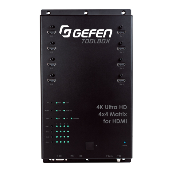
Page 6: Panel Layout
PANEL LAYOUT... -
Page 7: Using The 4X4 Hdmi Matrix
USING THE 4X4 HDMI MATRIX Connect all the sources to the HDMI inputs on the 4x4 HDMI Matrix, using the supplied cables. Connect the HDMI/DVI displays to the outputs on the 4x4 HDMI Matrix. Connect the 24VDC power supply to the 4x4 HDMI Matrix Controlling the 4x4 HDMI Matrix using the RMT16-IR: Pressing Buttons... -
Page 8: Rmt16-Ir Installation
RMT16-IR INSTALLATION 1. Remove battery cover from the back of the RMT16-IR remote. 2. Verify that dip switches 1 & 2 are in the down (OFF) position. 3. Insert the battery, hold the battery so that you can see the positive side facing up. The side that is not marked must be facing down. - Page 9 IR CODE CONFIGURATION Why would I need to change the remote channel? In some instances, the 4x4 Matrix for HDMI may use IR codes that confl ict with other IR remote control devices. The unit may switch inputs when another brand IR remote control is used or the RMT16-IR may cause other brand IR controlled devices to behave unexpectedly.
-
Page 10: Edid Management Feature
EDID MANAGEMENT FEATURE EDID. What is it and what is it used for? Under normal circumstances, an source device (digital and analog) will require information about a connected device/display to assess what resolutions and features are available. The source can then cater its output to send only resolutions and features that are compatible with the attached device/display. -
Page 11: Dip Switch Guidelines
Same as mode 6 but will record and store the EDID in memory. This EDID will persist no matter what displays are disconnected or reconnected thereafter. EDID will remain even upon power cycle. A user submitted EDID can be uploaded in this mode using a Gefen HDMI Signal Generator. - Page 12 RS-232 SERIAL COMMUNICATION What features are available via the RS-232 serial communications port? The 4x4 Matrix for HDMI can accept commands through the RS-232 serial communications port located on the rear panel. The current RS-232 control features are: • Switching/routing of inputs to outputs without the RMT16-IR remote control. •...
- Page 13 RS-232 SERIAL COMMUNICATION COMMANDS Switching/Routing Binary Table ASCII RMT16-IR Binary ASCII RMT16-IR Binary Button Button 0011 0001 0011 1001 0011 0010 0110 0001 0011 0011 0110 0010 0011 0100 0110 0011 0011 0101 0110 0100 0011 0110 0110 0101 0011 0111 0110 0110 0011 1000 0110 0111...
-
Page 14: 4X4 Hdmi Matrix Rack Mount Diagram
4x4 HDMI MATRIX RACK MOUNT DIAGRAM Rack mount ears are provided for installation of this unit into a 1U rack mount space. 1. Locate the side screws on the unit. 2. Remove the front 2 screws that are located closest to the front of the unit. -
Page 15: Specifi Cations
SPECIFICATIONS Video Amplifi er Bandwidth ................1.65 Gbps Input Video Signal ..................1.2 volts p-p Input DDC Signal ..................5 volts p-p (TTL) Single Link Range ................1080p / 1920 x 1200 HDMI Input/Output Connector ............Type A 19-pin Female Remote Control Port ............RS-232 Female, Mini-Stereo Power Consumption .................. -
Page 16: Terminology
TERMINOLOGY Short form for Display Data Channel. It is a VESA standard for communication between a monitor and a video adapter. Using DDC, a monitor can inform the video card about its properties, such as maximum resolution and color depth. The video card can then use this information to ensure that the user is presented with valid options for confi...
Need help?
Do you have a question about the 4x4 HDMI and is the answer not in the manual?
Questions and answers